10
Operating Modes
Mode 2 (Strobed Bi-Directional Bus I/O)
The functional configuration provides a means for communi-
cating with a peripheral device or structure on a single 8-bit
bus for both transmitting and receiving data (bi-directional
bus I/O). “Hand shaking” signals are provided to maintain
proper bus flow discipline similar to Mode 1. Interrupt gener-
ation and enable/disable functions are also available.
Mode 2 Basic Functional Definitions:
• Used in Group A only
• One 8-bit, bi-directional bus Port (Port A) and a 5-bit
control Port (Port C)
• Both inputs and outputs are latched
• The 5-bit control port (Port C) is used for control and
status for the 8-bit, bi-directional bus port (Port A)
Bi-Directional Bus I/O Control Signal Definition
(Figures 11, 12, 13, 14)
INTR - (Interrupt Request). A high on this output can be
used to interrupt the CPU for both input or output operations.
Output Operations
OBF - (Output Buffer Full). The OBF output will go “low” to
indicate that the CPU has written data out to port A.
ACK - (Acknowledge). A “low” on this input enables the
three-state output buffer of port A to send out the data. Oth-
erwise, the output buffer will be in the high impedance state.
INTE 1 - (The INTE flip-flop associated with
OBF). Con-
trolled by bit set/reset of PC4.
Input Operations
STB - (Strobe Input). A “low” on this input loads data into the
input latch.
IBF - (Input Buffer Full F/F). A “high” on this output indicates
that data has been loaded into the input latch.
INTE 2 - (The INTE flip-flop associated with IBF). Controlled
by bit set/reset of PC4.
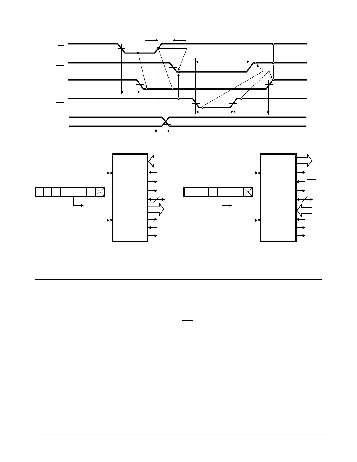
FIGURE 9. MODE 1 (STROBED OUTPUT)
tWOB
tWB
tAK tAIT
tAOB
tWIT
OBF
WR
INTR
ACK
OUTPUT
Combinations of Mode 1: Port A and Port B can be individually defined as input or output in Mode 1 to support a wide variety of strobed I/O
applications.
FIGURE 10. COMBINATIONS OF MODE 1
1
D7
0
D6
1
D5
1
D4
1/0
D3
D2 D1 D0
CONTROL WORD
PORT A - (STROBED INPUT)
PC4
8
OBFB
PA7-PA0
STBA
INTRB
PC0
PC6, PC7
2
WR
PC6, PC7
1 = INPUT
0 = OUTPUT
PORT B - (STROBED OUTPUT)
8
IIBFA
PC5
INTRA
PC3
ACKB
PC2
I/O
PC1
PB7, PB0
RD
10 1
D7
0
D6
1
D5
0
D4
1/0
D3
D2 D1 D0
CONTROL WORD
PORT A - (STROBED OUTPUT)
PC7
8
STBB
PA7-PA0
OBFA
INTRB
PC0
PC4, PC5
2
RD
PC4, PC5
1 = INPUT
0 = OUTPUT
PORT B - (STROBED INPUT)
8
ACKA
PC6
INTRA
PC3
IBFB
PC1
I/O
PC2
PB7, PB0
WR
11
82C55A