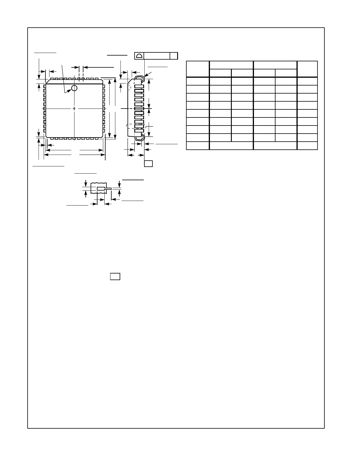
24
82C55A
Plastic Leaded Chip Carrier Packages (PLCC)
NOTES:
1. Controlling dimension: INCH. Converted millimeter dimensions
are not necessarily exact.
2. Dimensions and tolerancing per ANSI Y14.5M-1982.
3. Dimensions D1 and E1 do not include mold protrusions. Allow-
able mold protrusion is 0.010 inch (0.25mm) per side. Dimen-
sions D1 and E1 include mold mismatch and are measured at
the extreme material condition at the body parting line.
4. To be measured at seating plane contact point.
5. Centerline to be determined where center leads exit plastic body.
6. “N” is the number of terminal positions.
-C-
A1
A
SEATING
PLANE
0.020 (0.51)
MIN
VIEW “A”
D2/E2
0.025 (0.64)
0.045 (1.14)
R
0.042 (1.07)
0.056 (1.42)
0.050 (1.27) TP
EE1
0.042 (1.07)
0.048 (1.22)
PIN (1) IDENTIFIER
C
L
D1
D
0.020 (0.51) MAX
3 PLCS
0.026 (0.66)
0.032 (0.81)
0.045 (1.14)
MIN
0.013 (0.33)
0.021 (0.53)
0.025 (0.64)
MIN
VIEW “A” TYP.
0.004 (0.10) C
-C-
D2/E2
C
L
N44.65 (JEDEC MS-018AC ISSUE A)
44 LEAD PLASTIC LEADED CHIP CARRIER PACKAGE
SYM-
BOL
INCHES MILLIMETERS
NOTESMIN MAX MIN MAX
A 0.165 0.180 4.20 4.57 -
A1 0.090 0.120 2.29 3.04 -
D 0.685 0.695 17.40 17.65 -
D1 0.650 0.656 16.51 16.66 3
D2 0.291 0.319 7.40 8.10 4, 5
E 0.685 0.695 17.40 17.65 -
E1 0.650 0.656 16.51 16.66 3
E2 0.291 0.319 7.40 8.10 4, 5
N44 446
Rev. 2 11/97