4-12
The Special Mask Mode is set by OCW3 where: ESMM = 1,
SMM = 1, and cleared where ESMM = 1, SMM = 0.
Poll Command
In this mode, the INT output is not used or the microproces-
sor internal Interrupt Enable flip flop is reset, disabling its
interrupt input. Service to devices is achieved by software
using a Poll command.
The Poll command is issued by setting P = 1 in OCW3. The
82C59A treats the next
RD pulse to the 82C59A (i.e., RD =
0,
CS = 0) as an interrupt acknowledge, sets the appropriate
IS bit if there is a request, and reads the priority level. Inter-
rupt is frozen from
WR to RD.
The word enabled onto the data bus during
RD is:
W0 - W2: Binary code of the highest priority level request-
ing service.
I: Equal to a “1” if there is an interrupt.
This mode is useful if there is a routine command common to
several levels so that the
INTA sequence is not needed (saves
ROM space). Another application is to use the poll mode to
expand the number of priority levels to more than 64.
Reading the 82C59A Status
The input status of several internal registers can be read to
update the user information on the system. The following
registers can be read via OCW3 (lRR and ISR) or OCW1
(lMR).
Interrupt Request Register (IRR): 8-bit register which con-
tains the levels requesting an interrupt to be acknowledged.
The highest request level is reset from the lRR when an
interrupt is acknowledged. lRR is not affected by lMR.
In-Service Register (ISR): 8-bit register which contains the
priority levels that are being serviced. The ISR is updated
when an End of Interrupt Command is issued.
Interrupt Mask Register: 8-bit register which contains the
interrupt request lines which are masked.
The lRR can be read when, prior to the
RD pulse, a Read
Register Command is issued with OCW3 (RR = 1, RIS = 0).
The ISR can be read when, prior to the
RD pulse, a Read
Register Command is issued with OCW3 (RR = 1, RIS = 1).
There is no need to write an OCW3 before every status read
operation, as long as the status read corresponds with the
previous one: i.e., the 82C59A “remembers” whether the lRR
or ISR has been previously selected by the OCW3. This is
not true when poll is used. In the poll mode, the 82C59A
D7 D6 D5 D4 D3 D2 D1 D0
I----W2W1W0
EDGE
SENSE
LATCH
LTIM BIT
0 = EDGE
1 = LEVEL
V
CC
IR
8080/85
MODE
80C86/
88/286
MODE
INTA
FREEZE
INTA
FREEZE
FREEZE READ
IRR
WRITE
MASK
READ IMR
READ ISR
MASTER CLEAR
MASK LATCH
REQUEST
LATCH
IN - SERVICE
LATCH
NON-
MASKED
REQ
CLR
Q
SET
TO OTHER PRIORITY CELLS
PRIORITY
RESOLVER
CONTROL
LOGIC
SET ISR
CLR ISR
ISR BIT
QD
C
CLR
QD
CQ
CLR
SET
Q
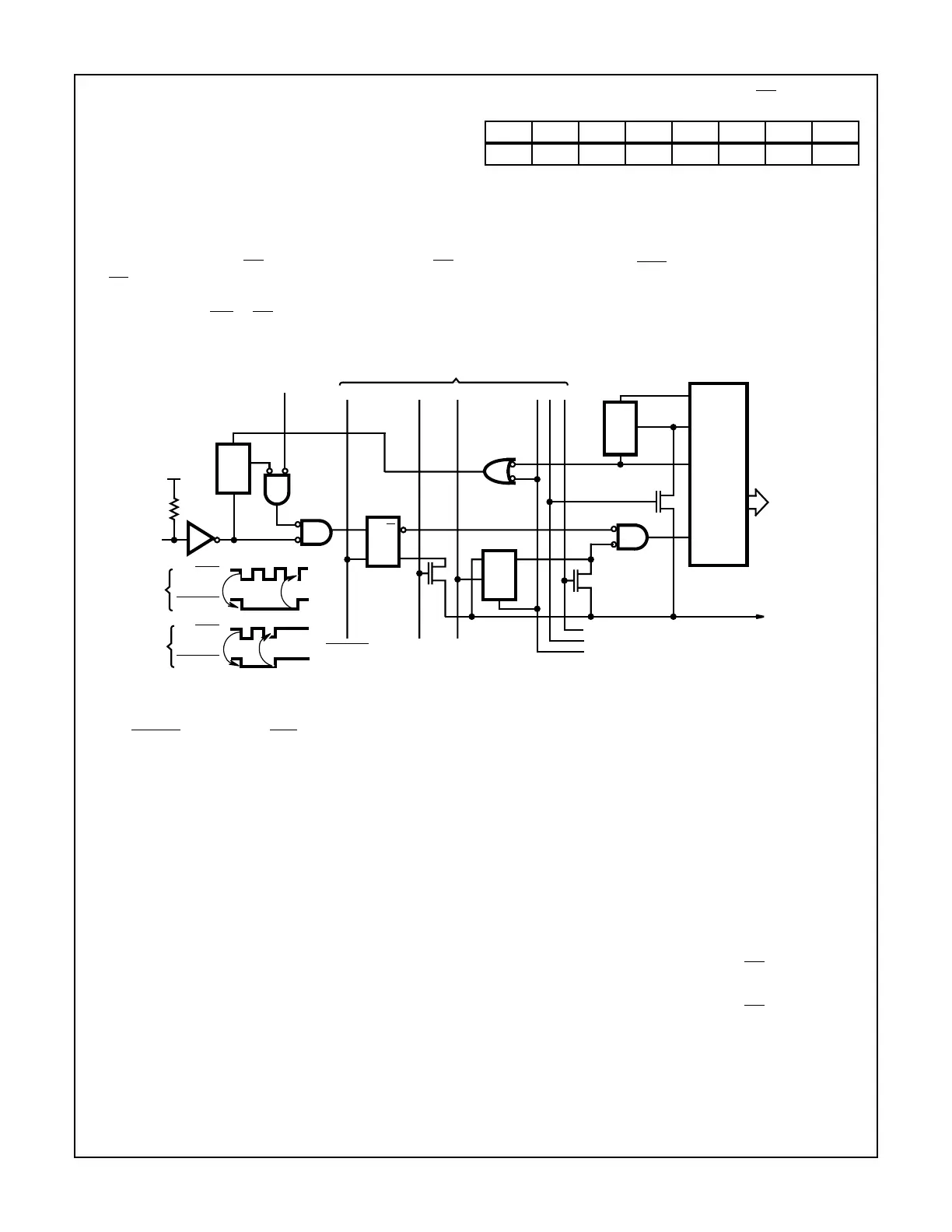
NOTES:
1. Master clear active only during ICW1.
2. FREEZE is active during INTA and poll sequence only.
3. Truth Table for D-latch.
FIGURE 9. PRIORITY CELL - SIMPLIFIED LOGIC DIAGRAM
C D Q Operation
1 D1 D1 Follow
0 X Qn-1 Hold
82C59A