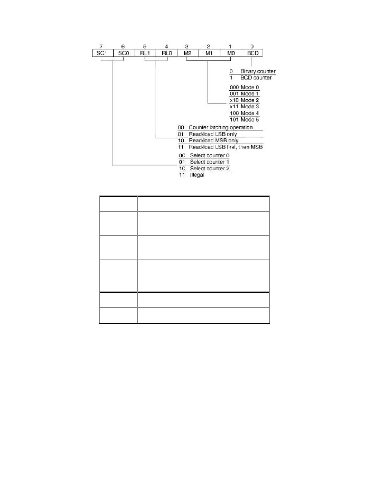
Mode 0: Interrupt on terminal count
Mode 1: Programmable one-shot ("alarm" type
pulse)
Mode 2: Rate generator (used to generate a regular
wave signal of a given period)
Mode 3: Square wave rate generator (used to
generate a regular square wave signal of a
given period)
Mode 4: Software triggered strobe
Mode 5: Hardware triggered strobe
The above figure gives us most of the information we need to write the correct control word to
the timer's control register to make it operate in the way we want. A few additional words of
explanation are also necessary, however. Some of the operation modes given in the table above
are fairly self-explanatory, but others are not so obvious. The various modes actually determine
the shape of the OUT signals for a particular timer. The 8253 PIT can generate various types of
square waves by holding the OUT line alternately high and low for given amounts of time. Such
output signals can be useful for determining timing for various kinds of applications, such as
delays. The data sheet for the timer gives timing diagrams for each of the modes. For our
application, we will only need to use Mode 0, since we want the timer to generate an interrupt
when it reaches zero.