80C187
System Configuration for 80186/
80187-Compatible Exception Trapping
When the 80C187 ERROR output signal is connect-
ed directly to the 80C186 ERROR
input, floating-
point exceptions cause interrupt
Ý
16. However, ex-
isting software may be programmed to expect float-
ing-point exceptions to be signalled over an external
interrupt pin via an interrupt controller.
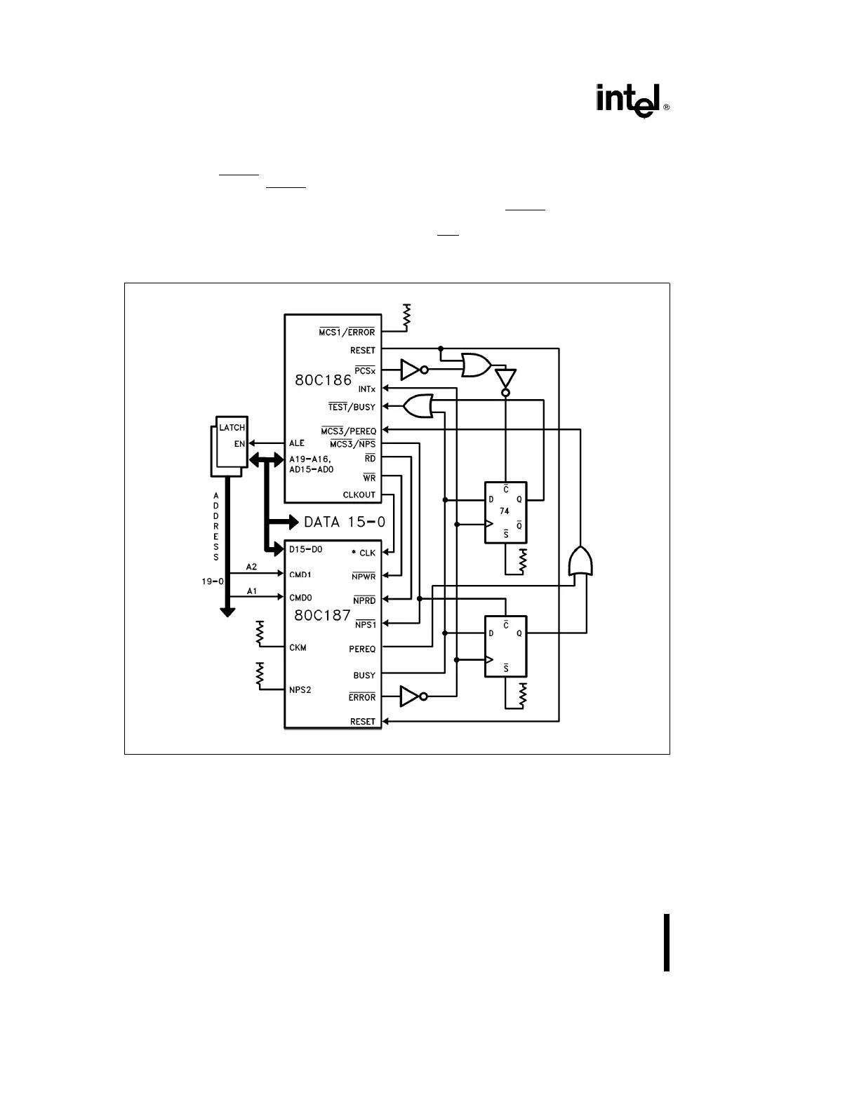
For exception handling compatible with the 80186/
82188/8087, the 80C186 can be wired to recognize
exceptions through an external interrupt pin, as Fig-
ure 10 shows. (Refer to the 80C186 Data Sheet for
an explanation of the 80C186’s signals.) With this
arrangement, a flip-flop is needed to latch BUSY
upon assertion of ERROR
. The latch can then be
cleared during the exception-handler routine by forc-
ing a PCS
pin active. The latch must also be cleared
at RESET in order for the 80C186 to work with the
80C187.
270640–8
*For input clocking options, refer to Figure 9.
Figure 10. System Configuration for 8087-Compatible Exception Trapping
20