EasyManua.ls Logo

JRC JMA-5104 User Manual

JRC JMA-5104
242 pages
To Next Page IconTo Next Page
To Previous Page IconTo Previous Page
Page #103 background imageLoading...
Page #103 background image
76
3.6.2 Operation procedures
1. Calling a function
Each time the
Each time the Each time the
Each time the [FUNC] key is pressed, the cursor moves in the following sequence:
key is pressed, the cursor moves in the following sequence: key is pressed, the cursor moves in the following sequence:
key is pressed, the cursor moves in the following sequence:
STANDARD
STANDARD STANDARD
STANDARD →
→→
→ FUNC1
FUNC1 FUNC1
FUNC1 →
→→
→ FUN
FUN FUN
FUNC2
C2 C2
C2 →
→→
→ FUNC3
FUNC3 FUNC3
FUNC3 →
→→
→ FUNC4
FUNC4 FUNC4
FUNC4 →
→→
→ STANDARD
STANDARD STANDARD
STANDARD
The title of the currently called mode is displayed at the upper right of the screen.
Suppose that signal processing settings are defined for FUNC1 with COAST as the title,
FUNC2 with DEEPSEA as the title, FUNC3 with FISHNET as the title, and FUNC4 with
RAIN as the title. Each time the [FUNC] key is pressed, the function titles are displayed at
the upper right of the screen in the order of COAST, DEEPSEA, FISHNET, and then RAIN.
You can confirm the currently selected function mode glancing at the screen.
2. Changing the setting of a function key
You can change the settings of a function key just as when performing general operation.
After the title displayed at the upper right of the screen is switched by pressing the [FUNC] key,
settings made in that status are stored as they are.
For example, if FUNC1 (COAST) is selected by pressing the [FUNC] key, the title COAST is
displayed at the upper right of the screen. This explains that the coast navigation function
mode is now active. Settings (e.g., signal processing settings and radar setting) made in the
mode are stored for FUNC1 (coast navigation mode).
3. Changing a function key title
The title displayed at the upper right of the screen can be easily changed.
Perform the procedure below to change any of the factory-set titles previously mentioned.
Take the following steps to change a function key title:
Take the following steps to change a function key title:Take the following steps to change a function key title:
Take the following steps to change a function key title:
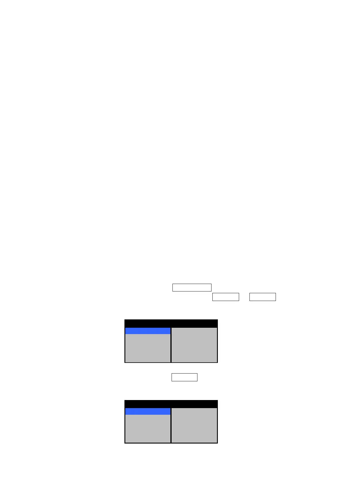
(a) Hold down the [FUNC] key to display the FUNCTION menu.
(b) The menu below is displayed. Select the function key FUNC1 to FUNC4 of which
title you want to change, and then press the [JOG DIAL] or [ACQ/ENT] key.
STANDARD >
FUNC1 >
FUNC2 >
FUNC3 >
FUNC4 >
FUNCTION
(c) The menu below is displayed. Select MODE , and then press the [JOG DIAL] or
[ACQ/ENT] key.
MODE > COAST
VIDEO >
TRAILS >
PULSE LENGTH >
INITIALIZE >
STANDARD

Table of Contents

Question and Answer IconNeed help?

Do you have a question about the JRC JMA-5104 and is the answer not in the manual?

JRC JMA-5104 Specifications

General IconGeneral
BrandJRC
ModelJMA-5104
CategoryMarine Radar
LanguageEnglish

Summary

Safety Information

Cautions for High Voltage

Details precautions for handling high voltage electronic equipment during maintenance.

Electric Shock First Aid

Provides instructions on what to do if someone experiences an electric shock.

First Aid Treatments

Outlines step-by-step first aid procedures for victims of electric shock.

Mouth-to-Mouth Respiration

Explains how to perform artificial respiration using the mouth-to-mouth technique.

Cardiac Massage

Details the procedure for cardiac massage, including combinations with artificial respiration.

Before Operation

Pictorial Indications and Symbols

Explains the meaning of various danger, warning, and caution symbols used in the manual and on the equipment.

Warning Labels

Notes the presence of a warning label on the equipment and advises against its removal or modification.

Operating Cautions

Cautions During Operation

Lists critical safety warnings and precautions to be observed while operating the radar equipment.

High Voltage Dangers

Highlights risks associated with high voltage components within the modulator and scanner units.

Equipment Appearance

Scanner Unit Models

Shows images and names of different scanner unit models (NKE-2042, NKE-2062, NKE-2102).

Processing and Control Units

Displays images and names of the processing unit (NDC-1260) and keyboard unit (NCE-7640).

Chapter 1: Introduction

Functions and Features

Describes the device's purpose, advanced performance, and user interface features.

System Composition and Diagrams

Details system components, attachments, spare parts, and general system diagrams.

Unit Configurations

Provides outline drawings and dimensions for various scanner, processing, and keyboard units.

Chapter 2: Keyboard and Menu Structure

Keyboard Layout and Functions

Explains the keyboard components (keys, knobs, jog dial, track ball) and their primary functions.

Key and Knob Operations

Details the functions of individual keys and knobs, including short and long press modes.

Jog Dial and Track Ball Usage

Explains the operation and modes of the jog dial and track ball for navigation and control.

Screen Display Elements

Illustrates and labels the various data and indicators shown on the radar PPI screen.

Menu Navigation and Structure

Guides users on how to open, close, and navigate through the radar's menu system hierarchy.

Chapter 3: Operation Procedures

Basic Operation Workflow

Outlines the fundamental sequence of operations: power-on, tuning, observation, and termination.

Power-On and Initial Setup

Details steps for powering on, tuning, and initial observation adjustments like brightness and language.

Core Radar Operations

Explains transmitting, halting, range changes, sensitivity adjustment, and interference elimination.

Advanced Operation Features

Covers clutter suppression, target measurement tools (VRM, EBL), motion displays, and trails.

Function Key and Menu Management

Explains the use of function keys for settings and managing system information and diagnostics.

Initialization and Troubleshooting

Details procedures for system initialization, special modes, and handling incomprehensible symptoms.

Chapter 4: Interpreting Radar Data

Target Detection Factors

Explains how target height and scanner unit height influence radar detection range.

Radio Wave Propagation and Obstructions

Discusses how radio waves are affected by terrain and weather, and how obstructions can block signals.

Understanding False Echoes

Identifies common causes of false echoes such as ghosts, side echoes, indirect echoes, multiple echoes, and radar interference.

Radar Transponder Display

Details how to display SART signals for locating survivors in distress situations.

Chapter 5: Maintenance and Inspection

General Equipment Maintenance

Covers basic cleaning, screw tightening, and connection checks for all units.

Unit-Specific Care

Provides specific cleaning instructions for scanner unit radiation sections and display units.

Troubleshooting Equipment Failures

Lists common issues, conceivable causes, and recommended actions for equipment abnormalities and breakdowns.

Chapter 6: After-sales Service

Repair and Warranty Information

Outlines procedures for requesting repairs, warranty coverage, and recommended maintenance inspections.

Radar Failure Checklist

Provides a checklist to assist in identifying and documenting radar malfunctions before requesting service.

Chapter 7: Disposal

Proper Equipment Disposal

Instructs on proper disposal methods for the equipment, batteries, and magnetrons according to regulations.

Chapter 8: Specifications

General and Unit Specifications

Lists general technical specifications and detailed specs for scanner, processing, keyboard, and display units.

Optional Equipment and Cable Specs

Details specifications for optional accessories and the lengths of connecting cables.

Chapter 9: Installation

General Installation Practices

Covers essential considerations for proper radar unit installation for optimal performance and maintenance.

Scanner Unit Installation Details

Provides guidance on selecting scanner unit locations and mounting procedures.

Indicator Unit and Cable Connections

Explains installing indicator units and connecting various cables, including GPS, NMEA, and PC.

Power Supply and Fuse Management

Covers changing ship's power settings and lists the types and ratings of fuses used in the equipment.

Post-Installation Checks and Adjustments

Outlines procedures for checking installation, operation, and performing necessary adjustments like azimuth and tuning.

Initialization and Receiver Settings

Guides on initializing the radar and configuring various receiver and GPS settings.

Advanced GPS and Sensor Settings

Details settings for DGPS, WAAS receivers, course/speed data input, and magnetic azimuth correction.

Related product manuals