135
To input NMEA data such as position information from the GPS equipment of JRC or a
different manufacturer by acquiring azimuth data from JLR-10, connect a cable from GPS
equipment using the connection method that is described in 9.3.9, "Connecting a GPS receiver
and NMEA equipment" or using a reserved cable, P3. Do not use the cable from JLR-10,
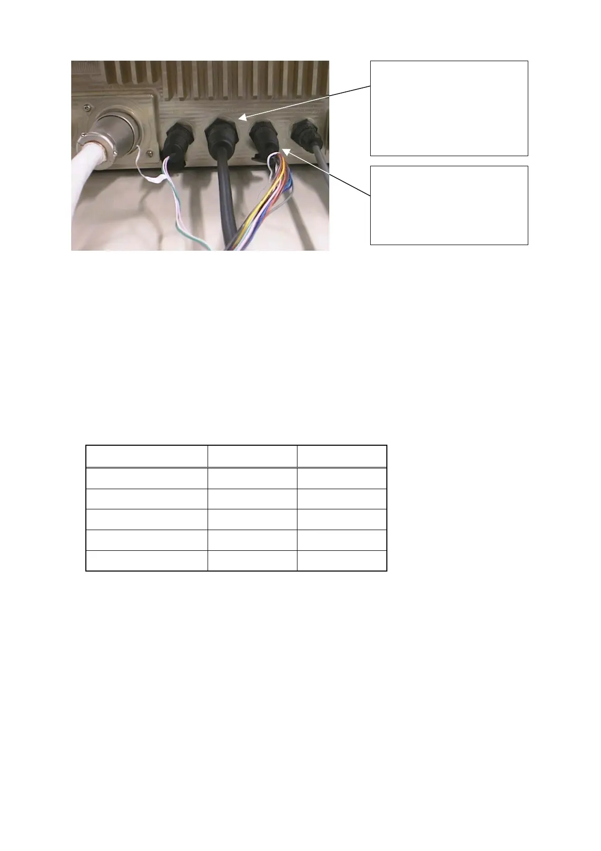
which is inserted in GPS(J3) input, as shown in Photograph 3.
2. When not using a dedicated cable
To connect azimuth information data from a GPS compass, use J5 8-pin connector P5
(LTWD09BFFA-L180) that is included in the main unit package.
See below for the connection method.
Signal name
GPS compass
connector side
Connector of
the equipment
Compass data input+ NC J5-1
Compass data input− NC J5-2
Compass data output+ RADAR-4 J5-3
Compass data output− RADAR-3 J5-4
GND RADAR-5 J5-5
The above information is related to the connection of azimuth data for JLR-10 only. For
position information, use the method that is described in 9.3.9, "Connecting a GPS receiver and
NMEA equipment".
Photograph 3
Insert the 6-pin connector o
CFQ-6934 with GPS (IND)
label attached to the connecto
of processing unit J3.
Insert the 9-pin connector o
CFQ-6934 with NSK(IND) label
attached to the connector o
processing unit J5.
 Loading...


