139
1. Connections to an external buzzer
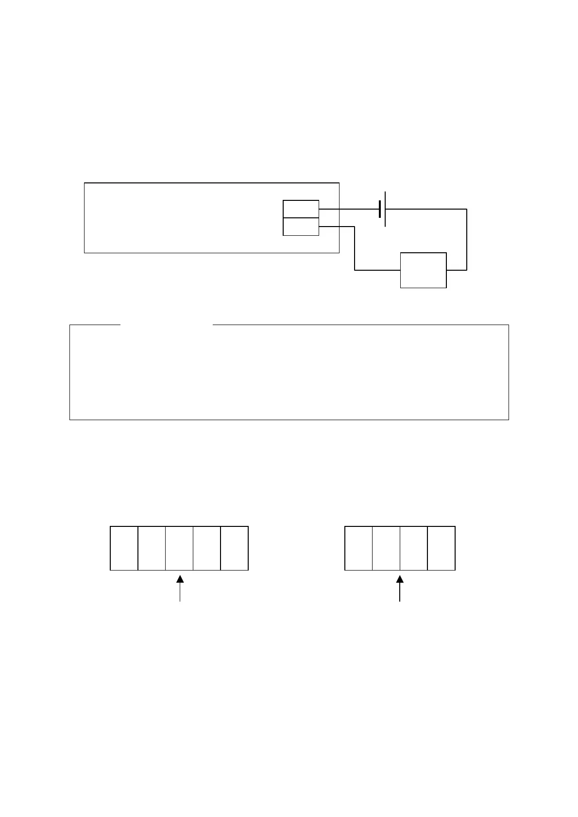
TB40 of the built-in PCB CSC-631 has a drycontact output, so that if the connection "TB-40 →
Power Supply → Positive terminal of the buzzer → Negative terminal of the buzzer → Power
supply ground" is made, then a buzzer can be sounded when there is an alarm from the
JMA-5100.
Connection Example
Caution
●
●●
● The maximum contact capacity is:
10A/250VAC
10A/30VDC
Make sure that this capacity is not exceeded.
2 Connections to a gyro and log
Connect the signal lines from a gyro and log to the CMJ-304C terminal board, then make the
settings on the followings.
CMJ-304C Terminal Board
CSC-631
TB40
Buzzer
Batter
etc.
1/R1
2/S1
3/S2
S3
5/R2
P+
P-
S+
S-
TB10
TB20
Connect the gyro signal line
(Synchro/Step)
Connect the log signal line
(Synchro/Step)

 Loading...


