2
1.3 Composition
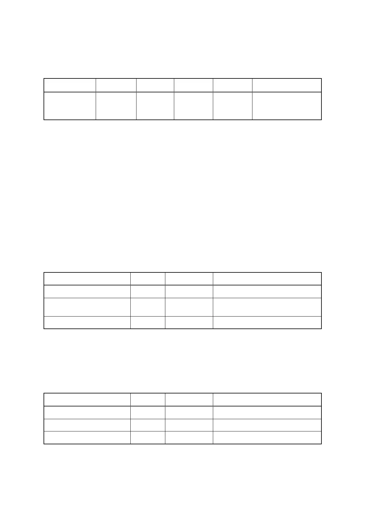
Radar configuration and ship's power
Comprehensive
model name
Scanner unit
Processing
unit
Keyboard
unit
Display unit Ship's power supply
JMA-5104
JMA-5106
JMA-5110
NKE-2042
NKE-2062
NKE-2102
NDC-1260 NCE-7640 NWZ-146
DC (12V/24V/32V )
DC (12V/24V/32V)
DC (24V/32V)
When an optional rectifier unit is used: (AC100V/110V/115V/200V/220V/230V) 50/60Hz single
phase
Rectifier unit model name (optional) : NBA-797
Note
When AC power supply is used, an optional rectifier unit is necessary.
The English presentation of the nameplate of each unit is as follows.
SCANNER UNIT
PROCESSING UNIT
KEYBOARD UNIT
DISPLAY UNIT
RECTIFIER UNIT
Attachments
Item name Quantity JRC code Remarks
Instruction manual 1 7ZPRD0590 This manual (English)
Cable between a scanner
unit and a processing unit
1 CFQ6912-20
19-core composite cable
Standard length 20m
Power cable 1 CFQ-6911-5 5m
Spare parts
Spare parts are provided for each of the indicator unit and the scanner unit.
The following table lists spare parts for each unit.
Spare parts for the indicator unit (7ZRD0010) included in the same package as the processing unit
Item name Quantity JRC code Remarks
Fuse (M60NR-10A) 3 5ZFAD00018 (Processing unit F1 : 10A)
6-pin connector 1 5JCDX00014 For NMEA data communication
8-pin connector 1 5JCDX00015 For NMEA data communication
Note
Only a 10A fuse is available for processing unit F1 (fuse for the indicator unit power) regardless of the
input power voltage and transmission output.
 Loading...


