122
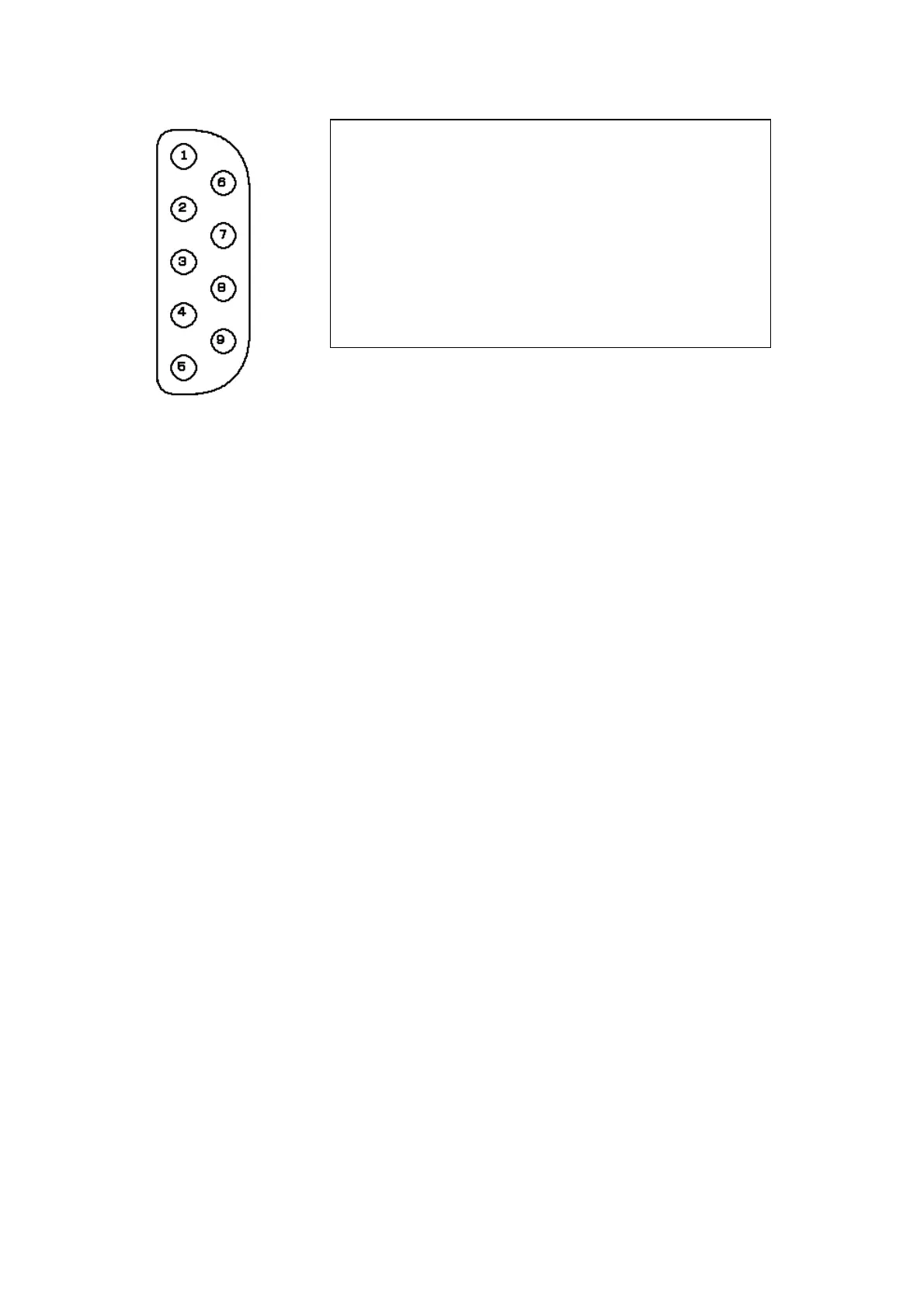
Connector for signal output to PC plotter/NMEA equipment (J8)
To PC plotter or NMEA equipment
(1) NC : Unused
(2) RSRXD : RXD signal input (reserved)
(3) RSTXD : NMEA signal output
(4) NC : Unused
(5) GND : Signal GND
(6) NC : Unused
(7) RSRTS : RTS signal output (reserved)
(8) RSCTS : CTS signal input
(2) RSRXD and (7) RSRTS are used for special purposes.
NMEA signals are output from (3) RSTXD and RS232C output is set at short circuit between 1
and 2 of power terminal block jumper TB1, and RS422 (NEMA0183) is set at short circuit
between 2 and 3. To connect J8 and a PC plotter (RS232C port), use a commercial cross type
DSUB9-pin cable (for RS232C).
To connect J8 to different NMEA equipment, also obtain a commercial DSUB9-pin connector.
In this case, make sure that the jumper of power terminal block TB1 is set between 2 and 3
(RS422 level).
 Loading...


