130
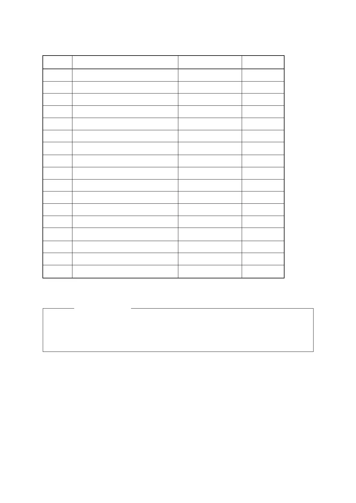
Connection table of cable CFQ-6912-20/30
Pin
number
Color Wire material Signal name
1 Blue thick, gray thick AWG16 2A
2 Purple thick, brown thick AWG16 2A
3 White thick, orange thick AWG16 1A
4 Red thick, green thick AWG16 1A
5 Black thick, blue thick AWG16 2A
6 Black AWG22 GND
7
Drain wire (coaxial) (drain wire:
Shielding, braided shielding)
AWG24 VDE
8 − − +12V
9 Yellow thick, pink thick AWG16 1A
10 Coaxial cable core AWG24 VD
11 Yellow AWG24 twisted pair COM+
12 Green AWG24 BZ
13 White AWG24 twisted pair COM−
14
Drain wire (shielding) (drain wire:
coaxial, braided shielding)
AWG24 TIE
15 Shielding wire core AWG24 TI
16 Orange medium AWG22 BP
Cover
Braided shielding (drain wire,
coaxial, drain wire shielding)
* Cable shape: 14mm ± 0.5mm
Caution
●
●●
● A cable is not connected to pin number 8, however, +12V is output to the
processing unit side. This voltage (+12V) is used when an external simulator is
connected.
The explanation up to this section covers the method in standard configuration. The next section
describes cable attaching methods when optional equipment is connected.
 Loading...


