2- 36 Keysight B2961A/B2962A SCPI Command Reference, Edition 6
Subsystem Command Summary
Setting Source Output and Measurement
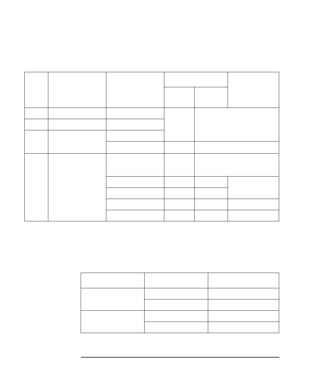
Source Output Ranges
Table 2-4 Voltage Output Range
Table 2-5 Limitations for using Channels 1 and 2
Range
value
Setting resolution
DC output voltage
or pulse peak/base
voltage
Maximum current
a
a. Table 2-5 shows the limitations when using Channels 1 and 2 for DC output or Pulsed output
with 50 μs ≤ t ≤ t
max
(=99.9999 ks).
Pulse width t
b
b. Maximum duty cycle is 99.9999 % for the pulse with 50 μs ≤ t ≤ t
max
, and 2.5 % for the pulse
with 50 μs ≤ t ≤ 1 ms, 50 μs ≤ t ≤ 2.5 ms, or 50 μs ≤ t ≤ 10 ms.
DC
output
Pulsed
output
0.2 V 0.1 μV 0 ≤ |V| ≤ 0.21 V ±3.03 A ±3.03 A with 50 μs ≤ t ≤ t
max
±10.5 A with 50 μs ≤ t ≤ 1 ms
2 V 1 μV 0 ≤ |V| ≤ 2.1 V
20 V 10 μV 0 ≤ |V| ≤ 6 V
6 V < |V| ≤ 21 V ±1.515 A ±1.515 A with 50 μs ≤ t ≤ t
max
200 V 100 μV 0 ≤ |V| ≤ 6 V ±3.03 A ±3.03 A with 50 μs ≤ t ≤ t
max
±10.5 A with 50 μs ≤ t ≤ 1 ms
6 V < |V| ≤ 21 V ±1.515 A ±1.515 A 50 μs ≤ t ≤ t
max
21 V < |V| ≤ 210 V ±105 mA ±105 mA
0 ≤ |V| ≤ 180 V ⎯ ±1.05 A 50 μs ≤ t ≤ 10 ms
0 ≤ |V| ≤ 200 V ⎯ ±1.515 A 50 μs ≤ t ≤ 2.5 ms
Channel 1 voltage V1 Channel 2 voltage V2
Current limit
a
a. I1: Channel 1 current, I2: Channel 2 current
0 < |V1| ≤ 6 V 0 < |V2| ≤ 6 V I1 + I2 ≤ 4 A
6 V < |V2| ≤ 21 V I1 + I2 × 1.6 ≤ 4 A
6 V < |V1| ≤ 21 V 0 < |V2| ≤ 6 V I1 + I2 × 0.625 ≤ 2.5 A
6 V < |V2| ≤ 21 V I1 + I2 ≤ 2.5 A