Keysight N9038A MXE Service Guide 237
RF Downconverter Section
RF Downconverter Section Troubleshooting
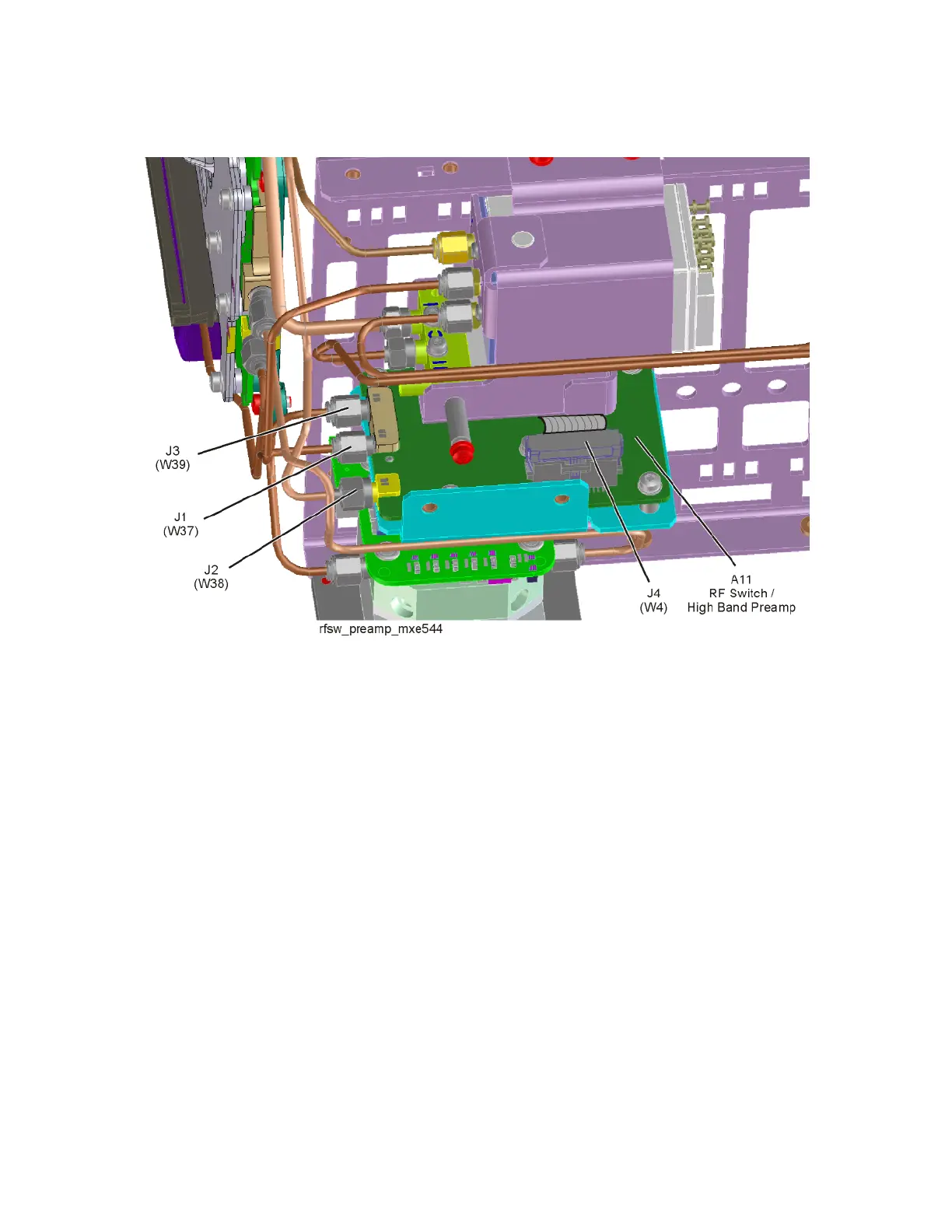
Figure 6-8 A11 RF Switch / High Band Preamp Connections - Option 544
6. Connect a signal generator to the A11 RF switch / High Band Preamp
assembly Input (J1).
7. Tune the signal generator to 100 MHz with an amplitude of -20 dBm.
8. Connect a spectrum analyzer to the A11 RF switch / High Band Preamp
assembly Low Band Output (J2).
9. Tune the spectrum analyzer to 100 MHz with a span of 1 MHz.
10.Turn the instrument self-alignment routine off by pressing System,
Alignments, Auto Align, Off.
11.Switch the A11 RF switch / High Band Preamp assembly to the low band
signal path by pressing FREQ, 50 MHz and SPAN, Zero Span.
12.Verify that the signal amplitude on the spectrum analyzer display is
approximately what is expected, as outlined in Table 6-6 or Table 6-7,
allowing for any additional test cable loss, as seen in Figure 6-9.

 Loading...


