278 Keysight N9038A MXE Service Guide
Front End Control
A15 Front End Control Assembly Troubleshooting
Verifying the Control for the A9 Input Attenuator A
1. Remove the instrument dress cover (MP24) and top brace (MP10). Refer to
Chapter 18, “Assembly Replacement Procedures.” for instructions on
removing these covers.
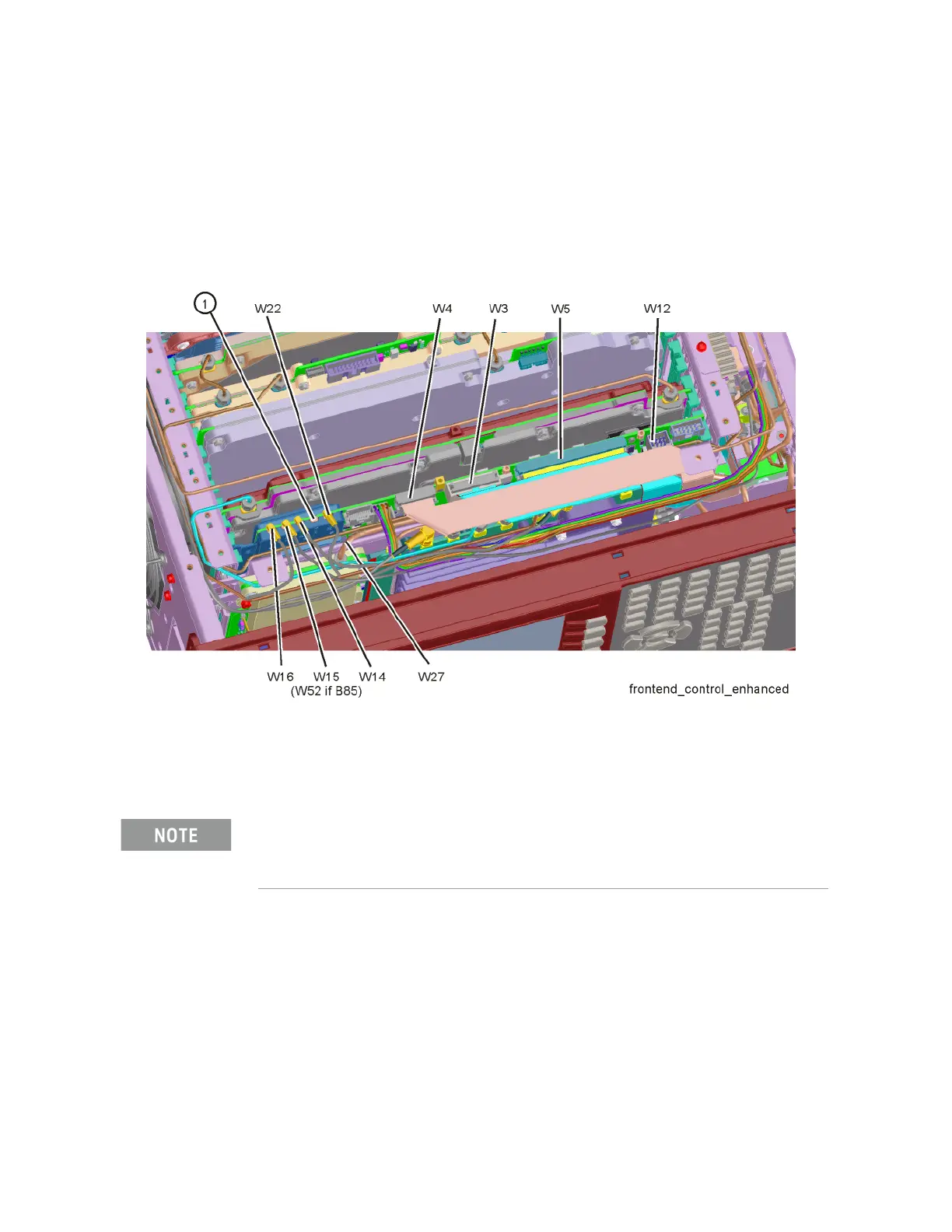
2. Disconnect cable W3 from J801 as shown in Figure 8-6.
Figure 8-6 A15 Front End Control Assembly Cable Locations
3. Connect the A9 / A10 Input Attenuator Control cable from J801 to the
Front End Control Test board J3 & J4 as shown in Figure 8-3.
4. Place the Front End Control Test board on a non-conductive surface.
5. Turn the instrument on and allow it to complete its boot up process,
ignoring any alignment failures.
6. Turn the instrument auto alignment routine off by pressing System,
Alignments, Auto Align, Off.
7. Tune the instrument to a Center Frequency of 50 MHz with a Span of 0 Hz
by pressing FREQ, 50 MHz and SPAN, Zero Span.
The 10 pin connector of the A9 / A10 Input Attenuator Control cable with the RED stripe on the
cable goes to J3 on the Front End Control Test board.

 Loading...


