286 Keysight N9038A MXE Service Guide
Front End Control
A15 Front End Control Assembly Troubleshooting
7. Referring to Figure 8-10, verify that all four of the power supply voltage
LEDs on the Front End Test board for the A11 RF Switch / High Band
Preamp assembly are on. If one or more of the power supplies is not on
verify the A6 Power Supply output voltages before replacing the A15 Front
End Control assembly. For information on verifying the A6 power supply
output voltages see Chapter 12, “Power Supply & Midplane.”.
The value for each of the power supply LEDs is shown in Table 8-6.
8. Verify that the serial communication interface for the A11 RF Switch /
High Band Preamp assembly identification on the A15 Front End Control
assembly is working properly by pressing System, Show, Hardware.
If there is a Low Band Switch entry on the Hardware Information screen
proceed to the next step. If not, there is most likely a problem with the A15
Front End Control assembly.
9. Tune the instrument to a frequency of 1 GHz with a span of 0 Hz by
pressing FREQ, 1 GHz, and SPAN, Zero Span.
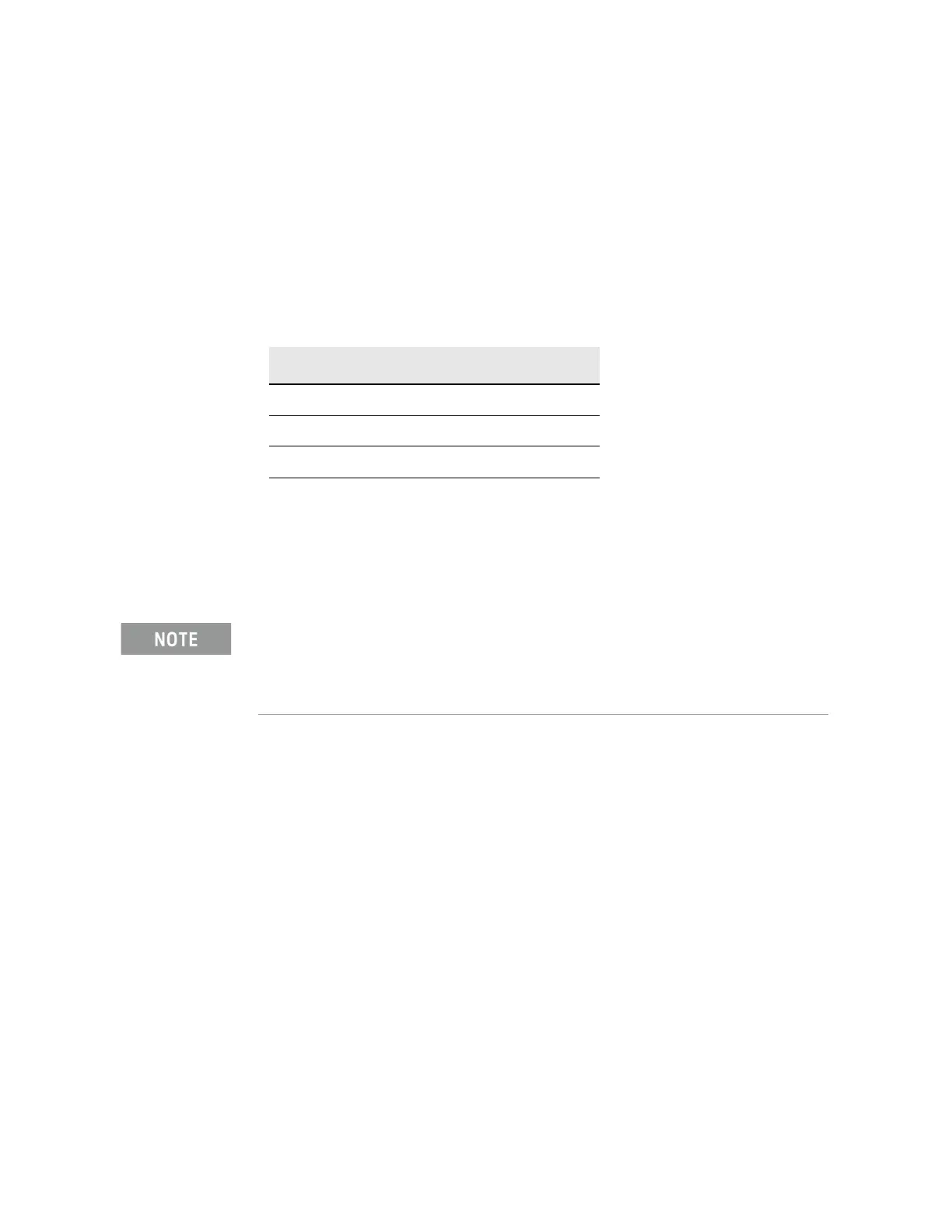
Table 8-6 A11 RF Switch / High Band Switch Power Supply Front End
Test Board LEDs
LED Power Supply Voltage
DS5 +15V
DS6 +9V
DS7 +5.2V
DS8 −15V
The Front End Control Test board has the circuitry on it to simulate the presence of an A11 RF
Switch / High Band Preamp assembly. When the instrument is booted up with the test board
connected it will return, via the serial communications interface, similar information to an actual
A11 RF Switch / High Band Preamp assembly. This information can then be viewed on the
instrument Hardware Information screen.

 Loading...


