290 Keysight N9038A MXE Service Guide
Front End Control
A15 Front End Control Assembly Troubleshooting
10.With the use of an ammeter measure the Main Coil Current being output
from the A15 Front End Control assembly by placing the two ammeter
probes across pins #1 and #2 of P8 on the Front End Control Test board, as
shown in Figure 8-11.
11.Verify that the current measured matches what is outlined in Table 8-8 for
the Frequency the instrument is tuned to.
If the measured current is correct proceed to the next step. If not, there is
most likely either a problem with the A12 YTF Preselector alignment or a
problem with the A15 Front End Control assembly. Perform the “A12 YTF
Preselector Alignment” routine as outlined below and then re-check the
main coil current levels.
12.Repeat step 9 through step 11 for the rest of the Frequency values listed in
Table 8-8.
13.If no trouble has been found with the main coil current coming from the
A15 Front End Control assembly, yet there is still a problem with the A12
YTF Preselector assembly, refer to Chapter 6, “RF Downconverter
Section.” for further troubleshooting information on the A12 YTF
Preselector assembly itself.
Be sure that the ammeter being used can handle the expected current level and that its range is
set properly prior to connecting it across the test points being measured.
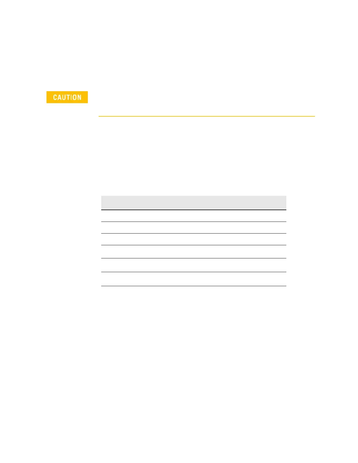
Table 8-8 A12 YTF Preselector Main Coil Tune Current Measurements
Frequency Main Coil Current Tolerance
4.0 GHz 85 mA ±20 mA
5.0 GHz 105 mA ±20 mA
8.0 GHz 165 mA ±25 mA
10.0 GHz
a
a. Option 526 Only
215 mA ±25 mA
15.0 GHz
a
325 mA ±30 mA
20.0 GHz
a
430 mA ±40 mA
26.5 GHz
a
560 mA ±50 mA

 Loading...


