Keysight N9038A MXE Service Guide 553
Assembly Replacement Procedures
RF Area - Option 503, 508, & 526
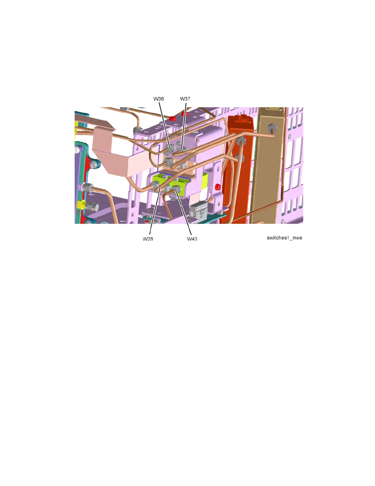
4. Refer to Figure 18-21. Replace cables W28, W36, W37, and W43.Torque
to 10 inch-lbs.
Figure 18-21 W28, W36, W37, W43 Cable Removal - Option 503, 508, & 526
5. Refer to Figure 18-7. Position the Chassis Right Side Outer bracket onto
the chassis and replace the sixteen screws (0515-0372). Torque to
9 inch-pounds.
6. Replace the top brace. Refer to the Top Brace and Power Supply Bracket
replacement procedure.
7. Replace the front panel. Refer to the Front Frame Assembly replacement
procedure.
8. Replace the instrument outer case. Refer to the Instrument Outer Case
replacement procedure.

 Loading...


