Chapter 4 MDP-621/641/640
Installation Operation manual
4.6 Power supply cable
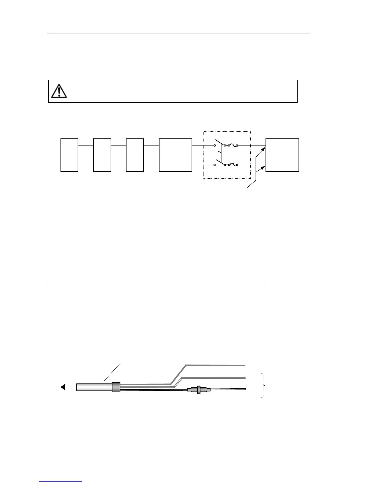
Power should be fed through a switch and protective fuses (or circuit breakers), as shown below.
WARNING: Do not apply over 31.2 VDC to the display unit or it may be damaged.
Generator
Switchboard Charger
Storage Battery
12/24V
Display Unit
DC voltage reference points
Main switch panel
(Knife Switch with Fuses)
Figure 4. 18 Recommended power supply connection
If you don not connect your radar to external equipment, tape the ends of the red and green wires.
Be certain to locate the fuse where it will be kept dry. And then plug the power supply cable into the
connector labeled "POWER" on the rear panel of the display unit.
When extending the power supply cable, size the wire as follows:
Boat Power Voltage Cable conductor Cable max. Length
Cross section
12Vdc 10 AWG (3.5 mm
2
) 3 m
8 AWG (6.0 mm
2
) 5 m
24Vdc 12 AWG (2.0 mm
2
) 6 m
10 AWG (3.5 mm
2
) 10 m
To power supply
Black
Gray
To display unit
Ground
White
DC+
DC-
Power supply cable
Figure 4. 19 Power supply cable
4-18 0093161022-06