CertusPro-NX SerDes/PCS Usage Guide
Preliminary Technical Note
FPGA-TN-02245-0.81 © 2020-2021 Lattice Semiconductor 109
All rights reserved. CONFIDENTIAL
Table 13.3. SerDes Power Pins Numbering
Electrical Idle
Electrical Idle is a steady state condition where the transmitter TxDP and TxDN voltages are held constant with the
same value. Electrical Idle is primarily used in power savings and inactive states. CertusPro-NX SerDes/PCS supports
three types of Electrical Idle: EI1, EI2, and EI4.
Electrical Idle I (EI1): In this case, both the transmitter output pins (TxDP and TxDN) are held to a steady-state
common-mode value and are held to have controlled low output impedance. This mode consumes higher power than
EI2 and EI4, but requires low recovery time since the AC-Coupling capacitor charge on the board is undisturbed.
Electrical Idle 2 (EI2): In this case, both the transmitter output pins (TxDP and TxDN) are held at 0 potential, but the
impedance of the transmitter is still as what is calibrated. DC current consumption of the driver stage is null. This has
the consequence of changing the Common Mode voltage from that of normal operation, and hence takes at least
100 µs to settle to or recover form assuming up to 200 nF AC-Coupling capacitor. This mode is mainly designed for PCIe
and SATA protocols.
Electrical Idle 4 (EI4): In this case, both the transmitter output pins (TxDP and TxDN) are held to a steady-state
common-mode value and are with controlled medium output impedance (about four times higher than EI1). This mode
consumes about a quarter of the power used by EI1, but requires more recovery time.
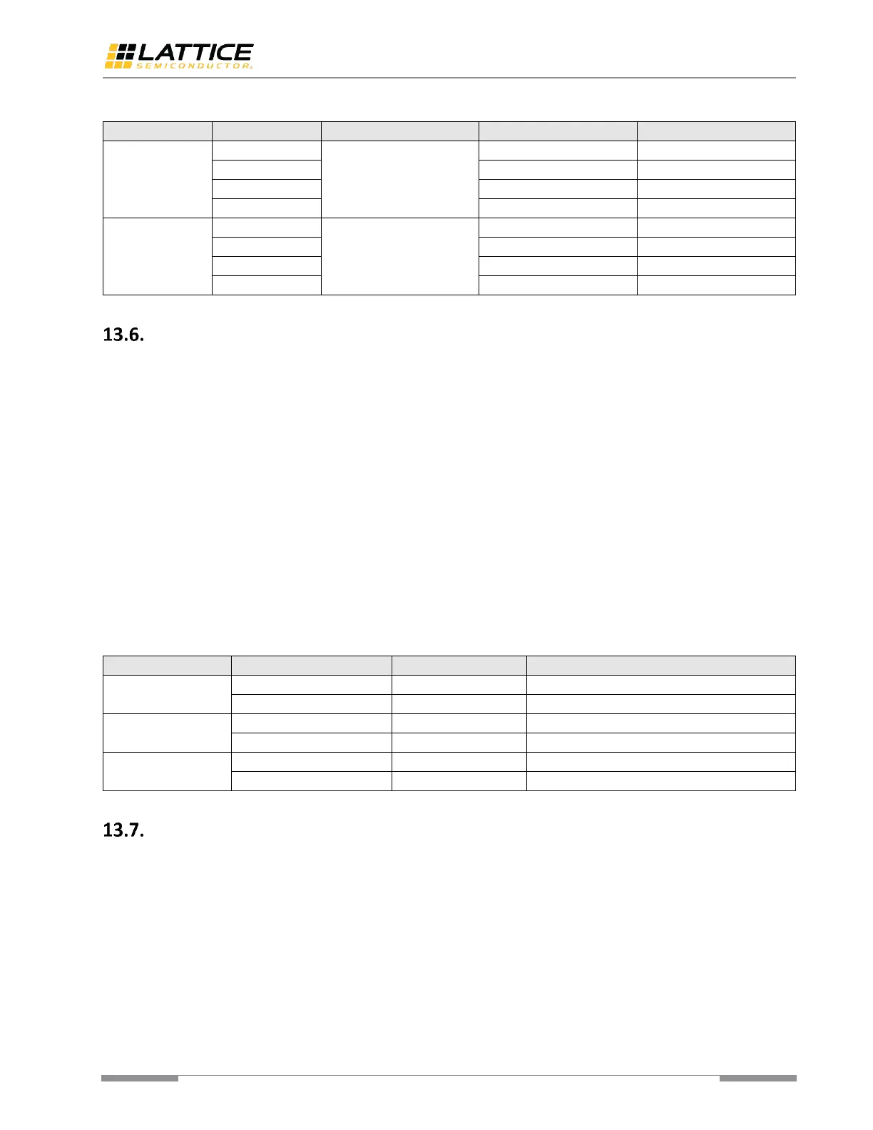
Table 13.4 shows the electrical idle usage in different SerDes/PCS modes.
Table 13.4. Electrical Idle Related Signals
Multiple Data Rate Support
There are only three pre-defined register groups for specific data rate (speed grade). These pre-defined register groups
are designed for PCI Express Gen3 mainly.
For protocols having more than three data rates and requiring dynamic switching such as CoaXPress, DisplayPort and
embedded DisplayPort, user logic need update the register setting if the target data rate is not in the pre-defined
register groups. However, it may have some impacts on the total time consumed by data rate switching under this
condition.
 Loading...