CertusPro-NX SerDes/PCS Usage Guide
Preliminary Technical Note
FPGA-TN-02245-0.81 © 2020-2021 Lattice Semiconductor 43
All rights reserved. CONFIDENTIAL
Control and Status Signals
Table 5.13 describes the control and status signals for 8B/10B PCS.
Table 5.14 describes the control and status signals for 64B/66B PCS.
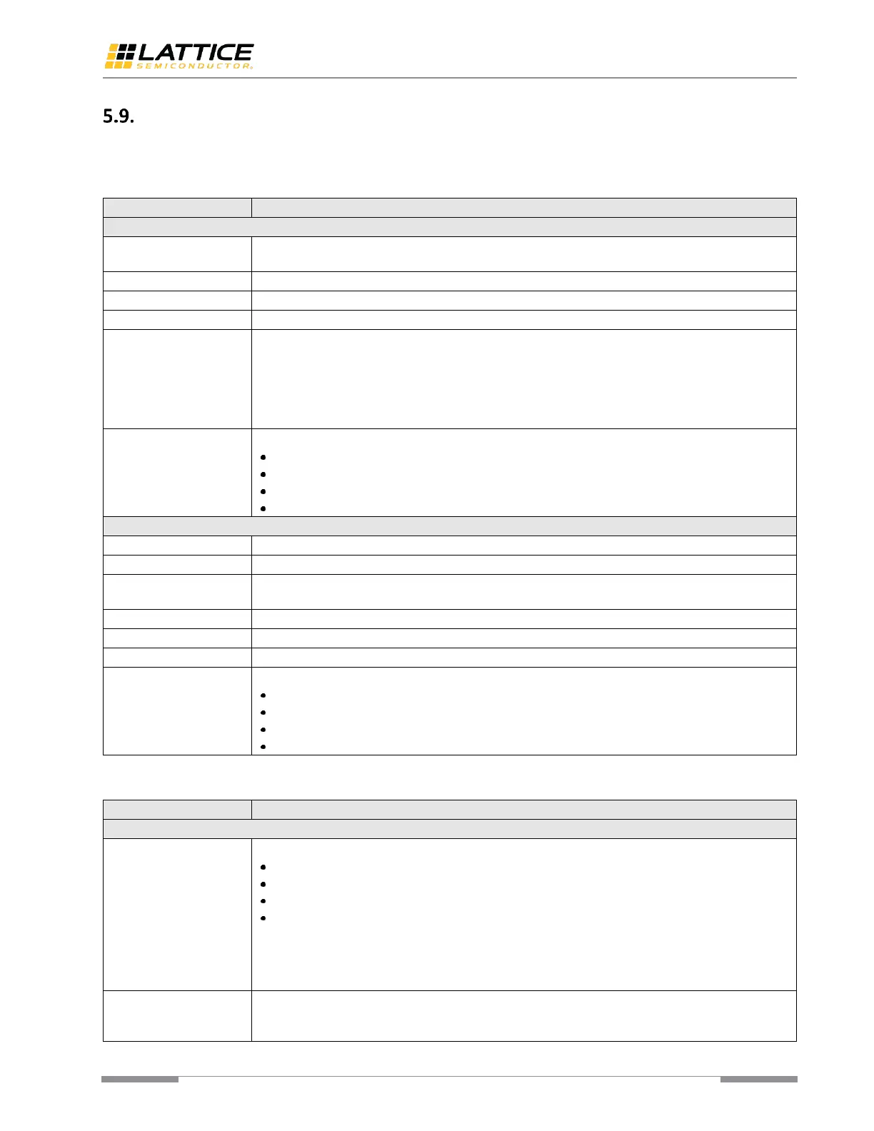
Table 5.13. Control and Status Signals Functions (8B/10B PCS)
The cordisp bit, used in GigE protocol to replace /I2/ symbol with /I1/, if the current running disparity
is detected as “positive”.
Active-high control character indicator.
Active-high signal which instructs the PCS to accept disparity value from tx_disval[3:0] input.
Disparity value supplied from FPGA logic. Valid when tx_frcdisp[3:0] is high.
Force 8B/10B encoder to output tx_data_8b data. When this signal is high, the corresponding
channel forces the 8B/10B encoder to output data from the input directly. In other words, the
output is the same as input. Note that the input of 8B/10B encoder is always 10 bits, the highest 2
bits are unused when 8B/10B encoder is enabled and tx_frcdata[3:0] is low.
This functionality is mainly implemented for applications like SLVS-EC that needs the ability to send
illegal 10b codes.
Tx FIFO status:
bit[3] – FIFO overflow.
bit[2] – FIFO underflow.
bit[1] – FIFO is almost full.
bit[0] – FIFO is almost empty.
The rundisp bit. Shows the running disparity status.
Active-high control character indicator.
Active-high signal driven by the PCS to indicate a disparity error was detected with the associated
data.
Code violation signal to indicate an error was detected with the associated data.
SKP added indication given by Elastic Buffer.
SKP deleted indication given by Elastic Buffer.
Rx FIFO status:
bit[3] – FIFO overflow.
bit[2] – FIFO underflow.
bit[1] – FIFO is almost full.
bit[0] – FIFO is almost empty.
Table 5.14. Control and Status Signals Functions (64B/66B PCS)
tx_control[7:0]/
tx_header[1:0]
8-bit control indication:
bit[0] – the control signal for tx_data_64b[7:0].
bit[1] – the control signal for tx_data_64b[15:8].
…
bit[7] – the control signal for tx_data_64b[63:56].
bit[1:0] of this signal can also be used as 2-bit block header. If “force data” signal is asserted, or if
64B/66B encoder is bypassed, bit[1:0] of this signal, along with the 64-bit payload forms a 66-bit
block which is usually generated by the 64B/66B encoder. In this case, bit[7:2] of this signal are not
used.
When this signal is asserted high, the 64-bit data (tx_data_64b) and 2-bit header (tx_control[1:0]) on
the same clock cycle are used to drive Tx Gear Box directly. The Encoder and Scrambler are bypassed
in this case.
 Loading...