CertusPro-NX SerDes/PCS Usage Guide
Preliminary Technical Note
FPGA-TN-02245-0.81 © 2020-2021 Lattice Semiconductor 153
All rights reserved. CONFIDENTIAL
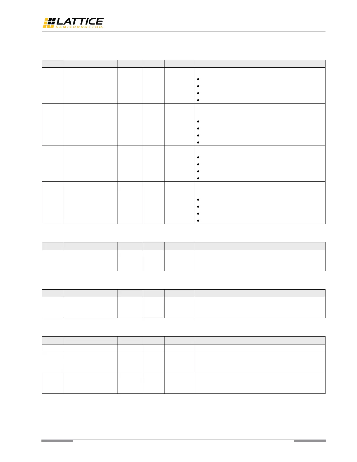
Table A. 128. MPCS BIST Control 1 [rege2]
BIST Channel Selector. Specifies the selected BIST Channel.
2’b11 – MPCS channel_3.
2’b10 – MPCS channel_2.
2’b01 – MPCS channel_1.
2’b00 – MPCS channel_0.
BIST Resolution selector. Specifies the selected BIST
resolution.
2’b11 – Less than 128 errors.
2’b10 – Less than 16 errors.
2’b01 – Less than 2 errors.
2’b00 – No error.
BIST Time selector. Specifies the selected BIST Time.
2’b11 – 100k cycles.
2’b10 – 5e+6 cycles.
2’b01 – 5e+9 cycles.
2’b00 – 5e+8 cycles.
BIST Sync Header Selector. Specifies the selected BIST sync
header counter selection.
2’b11 – 24
2’b10 – 14
2’b01 – 8
2’b00 – 5
Table A. 129. User Defined BIST Constant 1 Byte_0 [rege3]
User-defined BIST Constant 1 Byte_0 register reflects the
lower 8 bits of the 10b User-defined BIST Constant value
pattern 1.
Table A. 130. User Defined BIST Constant 1 Byte_1 [rege4]
User-defined BIST Constant 1 Byte_1 register reflects the
lower 8 bits of the 10b User-defined BIST Constant value
pattern 1.
Table A. 131. User Defined BIST Constant 1 MSByte [rege5]
User-defined BIST Constant 1 Byte_0 register reflects the
lower 8 bits of the 10b User-defined BIST Constant value
pattern 1.
User-defined BIST Constant 1 Byte_0 register reflects the
lower 8 bits of the 10b User-defined BIST Constant value
pattern 1.
 Loading...