CertusPro-NX SerDes/PCS Usage Guide
Preliminary Technical Note
60 © 2020-2021 Lattice Semiconductor FPGA-TN-02245-0.81
All rights reserved. CONFIDENTIAL
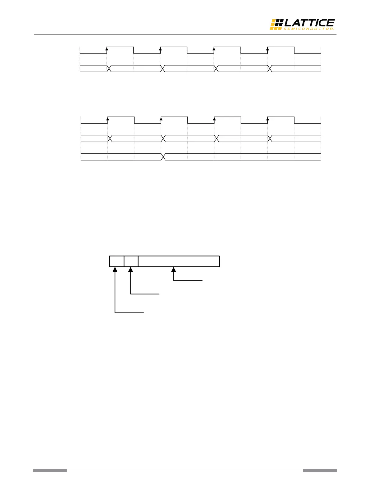
Figure 6.15. Data Stream before Word Alignment
After locking the data boundary, this module starts outputting aligned data: K28.5 followed by D16.2 (1010001001).
Seven bits are slipped in this example.
Figure 6.16. Data Stream after Word Alignment
However, the number of bit slipped is always zero in manual alignment mode considering that the bit shifting is
operated by PMA and controlled by fabric.
The length of synchronization code (or named synchronization detect pattern) can be configured as 1-byte, 2-byte or
4-byte. All bits of synchronization code are configurable and maskable. Once masked, the corresponding bit of
synchronization code is ignored during pattern matching. Primary and secondary synchronization code are provided
separately, and the secondary synchronization code can optionally be disabled.
The Link Synchronization FSM supports both 10-bit mode (bypassing 8B/10B decoder) and 8-bit mode (after 8B/10B
decoding) of input data. The bit mapping of 8-bit mode and 10-bit mode is shown in Figure 6.17.
Figure 6.17. Bit Mapping of Input Data
The first byte of synchronization code must appear on N-byte boundary, where N is the synchronization code length.
Once the synchronization code is detected, the Link Synchronization FSM applies this criterion to the validity check of
subsequent incoming data. Figure 6.18 shows the location where the first byte of synchronization code is expected to
appear.
 Loading...