CertusPro-NX SerDes/PCS Usage Guide
Preliminary Technical Note
FPGA-TN-02245-0.81 © 2020-2021 Lattice Semiconductor 55
All rights reserved. CONFIDENTIAL
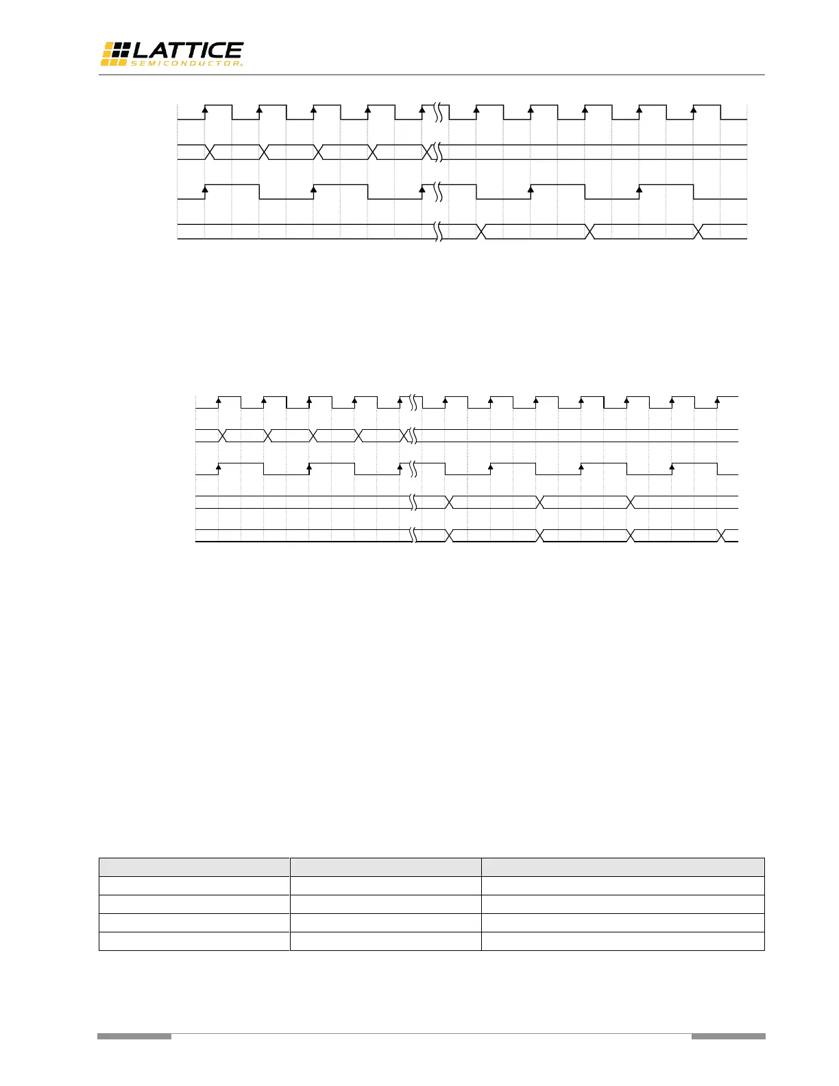
Figure 6.9. Rx Gearing Case II
This module can put the word alignment pattern (usually the control symbol) to the byte_0 (LSByte) of the 2-byte or
4-byte data bus. This byte-shifting feature can optionally be enabled. When byte-shifting feature is enabled, the
module reports that if the byte shifting happens. The byte-shifting feature is implemented for some protocols which
always have the special symbol to be aligned on an even-numbered code-group boundary.
Figure 6.10 shows how this feature work. A is the word alignment pattern. X is padding byte.
Figure 6.10. Byte Shifting for Word Alignment Pattern
The phase compensation FIFO resolves clock phase difference between its read side and write side. The write side and
read side clock should not have frequency difference. Otherwise, the FIFO overflow or underflow occurs. The phase
compensation FIFO can be bypassed. When bypassing, it works as synchronous DFF to launch the data to fabric.
8B/10B Encoder
This encoder performs the 8-bit to 10-bit code conversion along with maintaining the running disparity rules specified.
The functionality of this encoder is compatible with most 8B/10B PCS based protocols.
The 8B/10B encoder implements two modes: 1-byte mode and 2-byte mode. In 1-byte mode, encoder encodes one
8-bit input data in one clock cycle; in 2-byte mode, encoder encodes two 8-bit input data in one clock cycle.
Some protocols require the transmitter to start up with a certain disparity. The module allows you to replace the
current running disparity calculated by this module with the required disparity. The forced disparity can be used as the
start to calculate disparity for the subsequent 8b data.
The “Force Disparity” and “Invert Disparity” are controlled by two input signals: “tx_frcdisp” and “tx_dispval”. The
combinations of their values are listed in Table 6.5 below.
Table 6.5. Disparity Combinations
 Loading...