CertusPro-NX SerDes/PCS Usage Guide
Preliminary Technical Note
30 © 2020-2021 Lattice Semiconductor FPGA-TN-02245-0.81
All rights reserved. CONFIDENTIAL
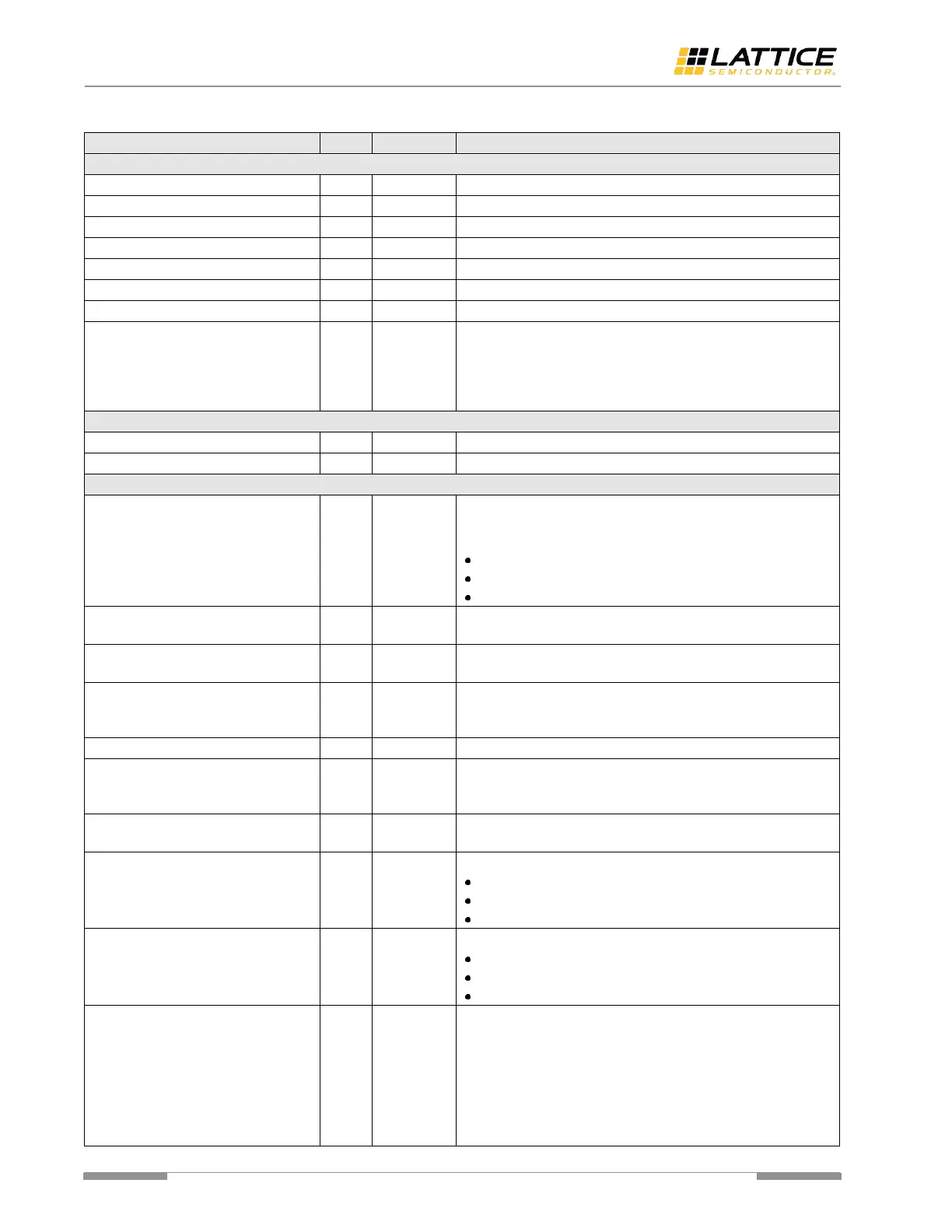
Table 5.8. EPCS Interface
User interface Rx clock input.
User interface Tx clock input.
Active low signal used to reset the Tx path of MPCS module.
Active low signal used to reset the Rx path of MPCS module.
Fundamental reset that triggers PCS auto calibration.
This low speed clock drives all calibration logic inside PMA
Controller. Connecting this clock port to epcs_tx_out_clk_o is
recommended. The recommended frequency range is
100-300 MHz. This clock should be stable and continuous after
power on.
For the signal mapping of this port, refer to Table 5.12.
For the signal mapping of this port, refer to Table 5.12.
PMA Control and Status Signals
This signal is used to put the PMA in powerdown mode. This
signal has only three states. This signal is required to be clocked
on mpcs_clkin_i.
2’b11 – deep low-power state.
2’b10 – low-power state.
2’b00 – operational state.
This signal is used to load Electrical Idle III in the Tx driver of the
PMA macro.
This port is used to signal the Electrical Idle condition detected
by the PMA control logic. This signal is driven by epcs_clkin_i.
This signal is used to report to PMA control logic where error
data is detected by the PCS logic. Asserting this signal leads CDR
PLL switch back to the process of frequency lock acquisition.
This signal is used to request the FOM evaluation.
This signal is used to handshake the FOM evaluation request in
EPCS mode. It is asserted for a single clock cycle by the PMA
Controller. This signal is synchronous to epcs_tx_out_clk_o.
This signal is the evaluated FOM result. This signal is
synchronous to epcs_tx_out_clk_o.
EPCS rates:
2’b10 – Rate2
2’b01 – Rate1
2’b00 – Rate0
EPCS current speeds:
2’b10 – Rate2
2’b01 – Rate1
2’b00 – Rate0
PHY transmit valid. This signal is used to transmit valid data. If
deasserted, the PMA macro is put in Electrical Idle 1. It can be
used for protocol requiring Electrical Idle, SATA, and must also
be deasserted as long as epcs_ready_o is not asserted. This
signal is also required to be generated one clock cycle earlier
than those corresponding epcs_tx_data_i signals.
epcs_txval_i = 0 causes the PMA Tx driver to generate the
Electrical Idle condition after 22 tx_pcs_clk cycles. If
 Loading...