CertusPro-NX SerDes/PCS Usage Guide
Preliminary Technical Note
154 © 2020-2021 Lattice Semiconductor FPGA-TN-02245-0.81
All rights reserved. CONFIDENTIAL
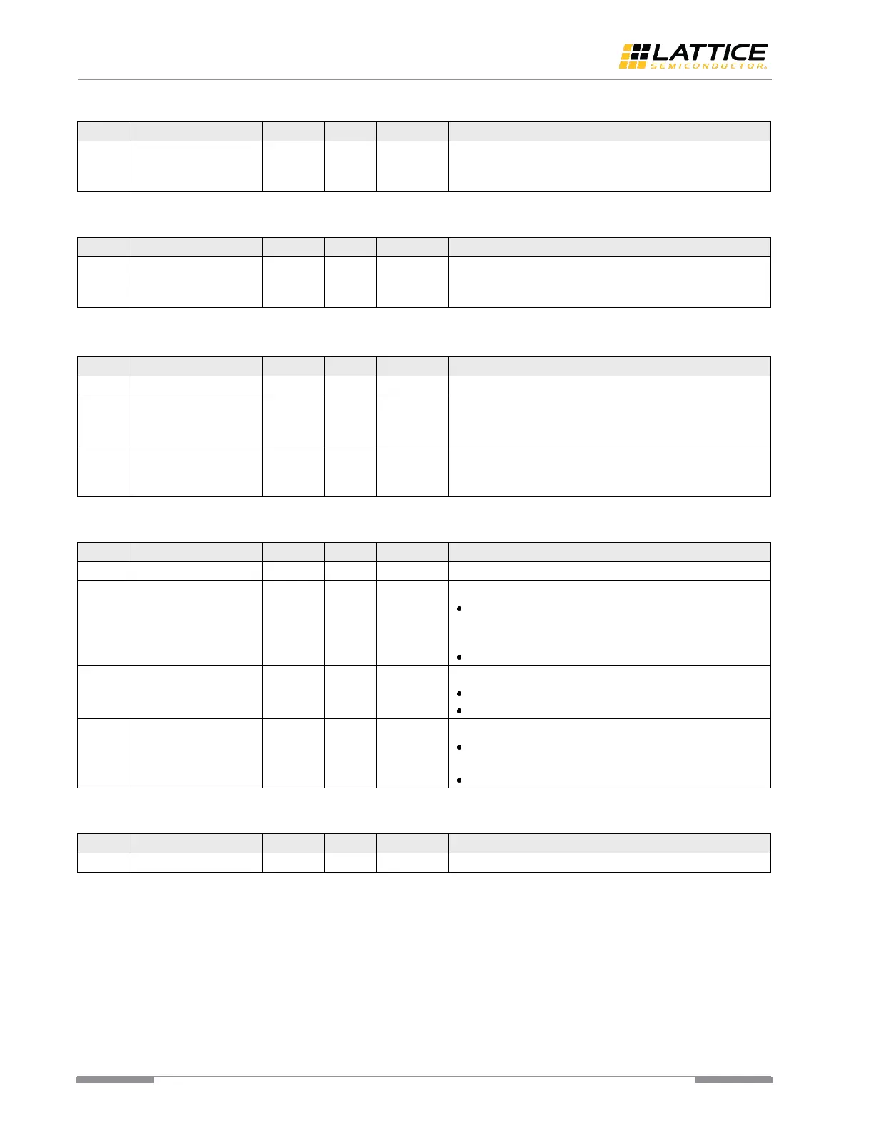
Table A. 132. User Defined BIST Constant 2 Byte_0 [rege6]
User-defined BIST Constant 1 Byte_0 register reflects the
lower 8 bits of the 10b User-defined BIST Constant value
pattern 1.
Table A. 133. User Defined BIST Constant 2 Byte_1 [rege7]
User-defined BIST Constant 1 Byte_1 register reflects the
lower 8 bits of the 10b User-defined BIST Constant value
pattern 1.
Table A. 134. User Defined BIST Constant 2 MSB [rege8]
User-defined BIST Constant 1 Byte_0 register reflects the
lower 8 bits of the 10b User-defined BIST Constant value
pattern 1.
User-defined BIST Constant 1 Byte_0 register reflects the
lower 8 bits of the 10b User-defined BIST Constant value
pattern 1.
Table A. 135. BIST Status 0 [rege9]
BIST Error Count. Specifies the BIST error count.
BIST mode. Specifies the BIST mode to be used.
1’b1 – No error for bist_res_sel = 0; Less than 2 errors
for bist_res_sel = 1; Less than 16 errors for bist_rel_sel
= 2 and less than 128 errors for bist_res_rel = 3
1’b0 – BIST is timed out or not started.
BIST Done. Specifies the status of BIST timer.
1’b1 – BIST timer expires.
1’b0 – BIST is ongoing or not started.
BIST Time Out. Specifies the BIST timeout status.
1’b1 – BIST is timed out, but it is still in “sync header
detection” stage.
1’b0 – BIST is ongoing or not started.
Table A. 136. BIST Status 1 [regea]
BIST Status 1 register reflects the BIST error count.
 Loading...