CertusPro-NX SerDes/PCS Usage Guide
Preliminary Technical Note
FPGA-TN-02245-0.81 © 2020-2021 Lattice Semiconductor 31
All rights reserved. CONFIDENTIAL
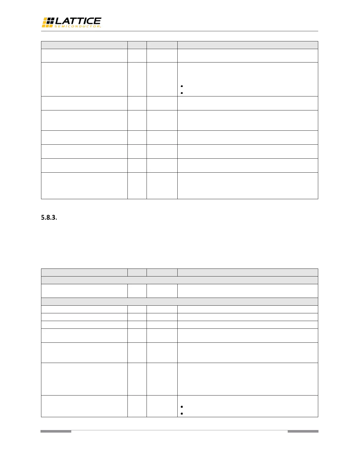
epcs_txval_i = 1, this operation causes the PMA Tx driver to exit
Electrical Idle condition 22 tx_pcs_clk cycles later.
PHY receive valid: this signal is used to signal receive valid data.
It corresponds to the two condition completed by the PMA
control logic:
Receiver detects incoming data (not in Electrical Idle);
CDR PLL is locked to input bitstream in fine grain state.
When asserted, this signal tells you that the PHY is ready to
transmit while using epcs_txval_i.
PHY ready. This signal is used to release the reset for the
external PCS and controller, and to start transmitting data to
PMA. This signal is driven by epcs_clkin_i.
This signal configure the activity detector to detect out-of-band
(OOB) accurately.
When asserted high, programmed de-emphasis is applied to the
transmitter driver.
This signal is used to report the PHY current power state. This
signal is driven by epcs_clkin_i.
PIPE control to SKIP 1 bit on receiver. When asserted, this
causes the receiver to freeze 1-bit clock. This function can be
used to control word alignment. This signal is considered as
asynchronous clock.
PIPE Interface
PIPE interface is accessible when SerDes/PCS is configured as PIPE mode. PIPE mode is designed to work with PCI
Express soft IP implemented by FPGA fabric. Table 5.9 shows the detailed PIPE interface descriptions. All the signals
listed in this table are per lane, and NL means the number of lanes. For the usage about Hardened PCI Express IP and
descriptions about TLP interface and UCFG interface, refer to CertusPro-NX PCI Express Hardened IP Core User Guide
(FPGA-IPUG-XXXXX).
Table 5.9. PIPE Interface
Auxiliary clock. This clock must be in any range from 1 MHz to
127 MHz and is required to sequence L1 substate and L1.P2
PCIE-Express PIPE Interface
Open drain bidirectional CLKREQ# input.
Open drain bidirectional CLKREQ# output.
Open drain bidirectional CLKREQ# output enable
PHY reset. This signal is used to reset the complete SerDes
macro and the associated PMA control logic.
PCLK clock generated by the PHY macro. This signal is a per-lane
signal which is provided by the PHY macro to the PCI Express
controller and PMA Controller.
PCLK used by the PCS logic and PMA control logic. This signal is a
per-lane signal which is used by the PCIe PCS logic as well as by
the PMA control logic for calibration purpose for instance. The
recommended frequency range for this clock is from 100 MHz
to 300 MHz.
This signal is synchronous to pipe_clkin_i. PIPE rates:
2’b10 – Gen3
2’b01 – Gen2
 Loading...