CertusPro-NX SerDes/PCS Usage Guide
Preliminary Technical Note
FPGA-TN-02245-0.81 © 2020-2021 Lattice Semiconductor 123
All rights reserved. CONFIDENTIAL
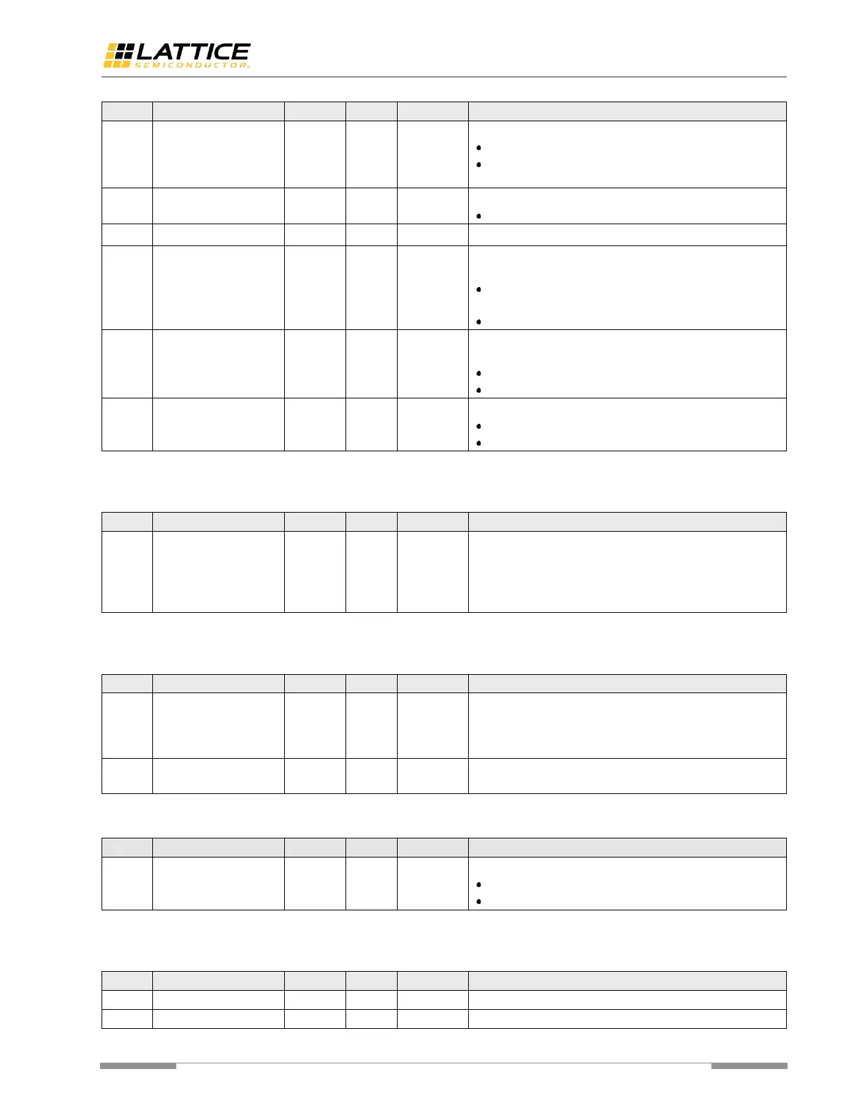
always detected.
1’b1 – the result is always detected.
1’b0 – normal operation (this bit should be set to 1’b0
for other protocols).
Defines the CDR PLL reference clock mode.
2’b00 – normal operation.
Defines the frequency comparator threshold value when
CDR is configured in PMA driven mode.
1’b1 – Rx clock and Tx clock must be in 0.8% difference
range.
1’b0 – 0.4%
Defines the Schmitt trigger signal detection threshold used
to detect Electrical Idle on Rx.
1’b1 – threshold is 180mV (±33%)
1’b0 – threshold is 125mV (±40%)
Tx PLL reference clock source selection.
1’b1 – driven by CDR PLL loop feedback clock.
1’b0 – normal operation.
Note: This register can be reprogrammed when the PHY is under reset or when calibration has completed (PMA is ready).
Table A. 3. Clock Count for Error Counter Decrement [reg01]
In PCS driven mode, the PMA control logic counts the
number of errors detected by the PCS logic in order to
decide how to switch back to frequency lock mode of CDR
PLL. This counter is used to decrement the error counter
every 16*errcnt_dec[7:0] TxClk clock cycles.
Note: This register can be reprogrammed when the PHY is under reset or when calibration has completed (PMA is ready).
Table A. 4. Error Counter Threshold – Rx Idle Detect Max Latency [reg02]
Defines the number of clock cycles required by the Loss of
Signal detect logic. The least value is 4’h3, because the
Loss of Signal output is considered as metastable by the
PCS logic.
Defines the error counter threshold value after which the
CDR PLL switches back to frequency lock.
Table A. 5. Rx Impedance Ratio [reg03]
Tunes the Rx impedance ratio of the PMA.
8’h80 – 100 Ω
8’h55 – 150 Ω corresponds to 2/3 ratio
Note: This register can be reprogrammed when the PHY is under reset or when calibration has completed (PMA is ready).
Table A. 6. Tx PLL F Settings and PCLK Ratio [reg04]
Defines the ratio between PCLK and TxClk (PMA Clock
 Loading...