CertusPro-NX SerDes/PCS Usage Guide
Preliminary Technical Note
FPGA-TN-02245-0.81 © 2020-2021 Lattice Semiconductor 91
All rights reserved. CONFIDENTIAL
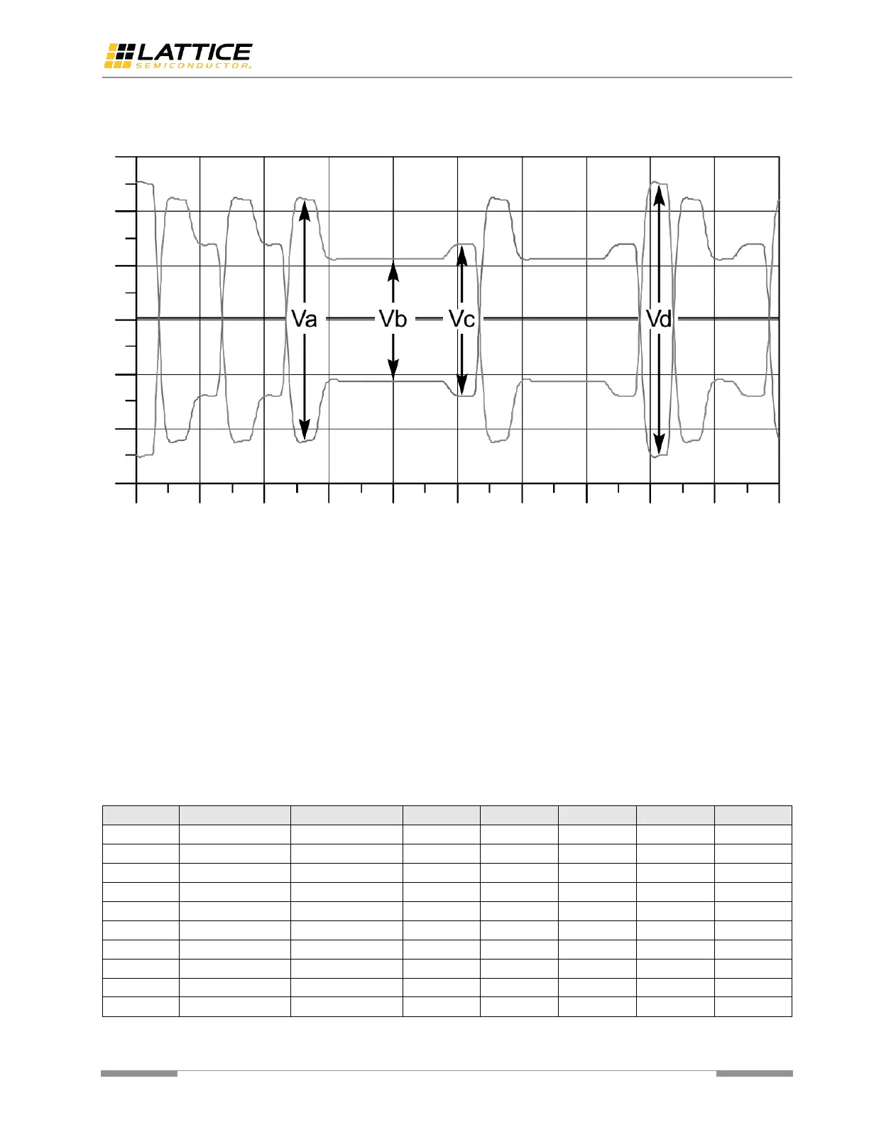
Given a differential signal with symmetric swings above and below 0, it can be seen from Figure 8.5 that there are four
possible output values in each positive or negative directions. Table 8.1 shows the positive normalized voltage levels.
Figure 8.5. Definition of Tx Voltage Levels
The de-emphasis is defined as
.
Moreover, the pre-shoot is defined as
.
Table 8.2 shows the Tx preset ratios and corresponding coefficient values defined by PCI Express Specification. For
protocols that only require de-emphasis feature, the pre-cursor ratio (C
–1
) should be fixed as zero. For example, to
achieve –3.5dB de-emphasis, post-cursor ratio (C
+1
) should be set as –0.167 and pre-cursor ratio (C
–1
) should be set as
0.000.
The pre-cursor ratio (C
–1
) and post-cursor ratio (C
+1
) can be configured via PMA registers (reg0a and reg0b). After these
registers have been updated, the mpcs_txdeemp_i or epcs_txdeemp_i port should be asserted and then writes 1 to the
bit 0 of PMA register (reg80) to trigger a new computation of PMA settings based on the current value in related
registers.
Table 8.2. PCIe Tx Preset Ratios and Corresponding Coefficient Values
 Loading...