HOISTS 2250 SERVICE/MAINTENANCE MANUAL
5-20
Published 07-19-16, Control # 249-01
Disassembling the Cylinder
See Figure 5-15 for the following procedure.
1. Remove the four socket head capscrews (1).
2. Working in a crisscross manner, alternately loosen the
nuts (2) on the threaded rods (3) until the bonnet (4) is
removed from the cylinder (5). Make sure the threaded
rods do not back out when loosening the nuts.
3. Disassemble the cylinder using the illustration as a
guide.
Assembling the Cylinder
See Figure 5-15 for the following procedure.
1. Apply Loctite #263 to the exposed threads of the
threaded rods (3) and apply Loctite #243 to the threads
of the socket head capscrews (1).
2. Lubricate all parts with a light coat of air cylinder grease.
3. Assemble the cylinder (5) and observe the following
precautions:
- The piston rod (6) must be flush with the back edge
of the piston (12).
- The packing cup (7) must be snug against the back
side of the piston.
- The vent hole in the bonnet (4) must be positioned
180° from the air inlet hole (8) in the cylinder.
4. Align the holes in the bonnet with the threaded rods and
install the nuts (2).
5. Working in a crisscross manner, alternately tighten the
nuts on the threaded rods until the bonnet flange is tight
against the cylinder flange.
6. Securely install the four socket head capscrews.
Installing the Cylinder
See Figure 5-14 for the following procedure.
1. Pin the air cylinder (13) to the clutch spider (10) so the
air inlet port is toward the outside. Make sure to install
the cotter pin.
2. Connect the air line (12) to the cylinder.
3. Block the cylinder in position.
4. Stand clear of the clutch and release the clutch. The
cylinder rod (17) will extend. See the procedure in Table
5-1.
5. Pin the cylinder rod to the clutch lever (4). Make sure to
install the cotter pin.
6. Apply the clutch. See the procedure in Table 5-1
.
7. Adjust the clutch.
8. Install the guard (3) over the drum flange and clutch
assembly.
9. Adjust the brake band supports (5) to provide the proper
drum-to-lining clearance.
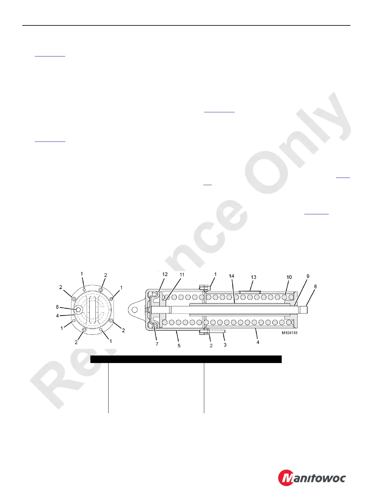
FIGURE 5-15
Item Description Item Description
1 Socket Head Capscrew (qty 4) 8 Air Inlet Hole
2 Nut (qty 4) 9 Bushing
3 Threaded Rod (qty 4) 10 Spring
4 Bonnet 11 Spring Guide
5 Cylinder 12 Piston
6 Piston Rod 13 Warning Plate
7 Packing Cup 14 Spacer
 Loading...


