4 Chapter 1: Introduction
PRO Series Live Audio Systems
Owner’s Manual
Conventions
• Hand symbols, such as, (pushbutton, trackball etc.) and (control knob), are
used to show the operation of the physical controls on the control surface. GUI
operation is indicated by a pointer , which represents a ‘click’ operation.
• The graphics shown right are used to differentiate between diagrams of
the control surface (immediate right) and GUI (far right). Placement is
generally towards the upper-right corner of the diagram.
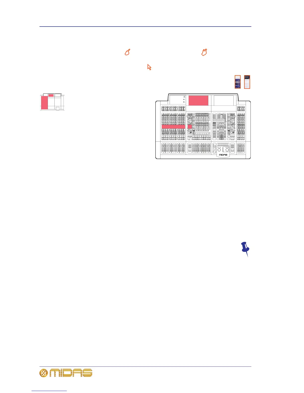
• Outline drawings are strategically
placed throughout the manual to
reference information to the
appropriate area(s) on the control
surface/GUI of the PRO Series
Control Centre. The small version
(left) indicates bay and GUI location,
while the larger one (right) can
pinpoint control sections (for
example, the EQ areas of the
12-channel input bay shown right).
Target areas are shaded in red.
• Unless otherwise stated, illumination
of a control (pushbutton, switch, control knob etc.) on the control surface/GUI of a
PRO Series Control Centre indicates an “on”, “active” or “enabled” state. Conversely,
an extinguished condition indicates the control is “off”, “inactive” or “disabled”.
• The following types of pushbutton are used on the control surface:
• “switch” - a latching pushbutton, that is, one that changes its on/off status.
• “button” - a non-latching pushbutton.
• “key” - a keyboard-type pushbutton. Usually used for entering data, such as a
number or character.
• Generally, control names are the same whether they are on the control surface or
the GUI. However, in cases where they differ, both names will be given, separated
by a forward slash “/”. The control name shown on the GUI will always be last and
enclosed in square brackets “[]”.
• Hints and tips are used to convey useful information to the user. These have
a drawing pin graphic (shown right) next to them.
Terminology
To support both FOH and MON use, the terminology has been chosen very carefully to
apply equally to both (see "Glossary" on page 617). For a definition of the primary
buses on the PRO Series Control Centres, see “Definition of the primary buses” on
page 417.