Front and rear panel connections 31
PRO Series Live Audio Systems
Owner’s Manual
Each GUI screen has its own default display, although either is selectable via the GUI
main menu. The Overview screen displays 12 inputs and two sets of eight outputs,
and the Meters screen shows all the meters, four inputs and a summary of the
automation. Both screens have a banner at the top, which is constantly displayed, and
a channel strip down the outermost side.
The channel strips have a similar function to the ones on the control surface (see
Figure 5 on page 29), but provide extra functionality. Each displays an ‘overview’ of
the associated selected channel, which is divided into specific sections that provide
access to processing areas.
Front and rear panel connections
The control centre has connector panels on both the front and rear, and also to the left
of the mix bay GUI screen.
The connector panel to the left of the GUI has an XLR socket and two USB sockets for
connecting a talk mic and USB devices, respectively. For example, you can connect a
USB memory stick for show file backup and transfer, or a USB keyboard for text editing
on the GUI. The top USB socket is associated with the mix bay and the bottom one with
the master bay.
There are two panels at either end of the front of the control centre, under the
armrests. Each has a keyboard and phones socket. The left and right keyboard sockets
operate the mix and master bay GUI screens, respectively. The phones socket in the
left panel is for the monitor A section and the other one is for monitor B.
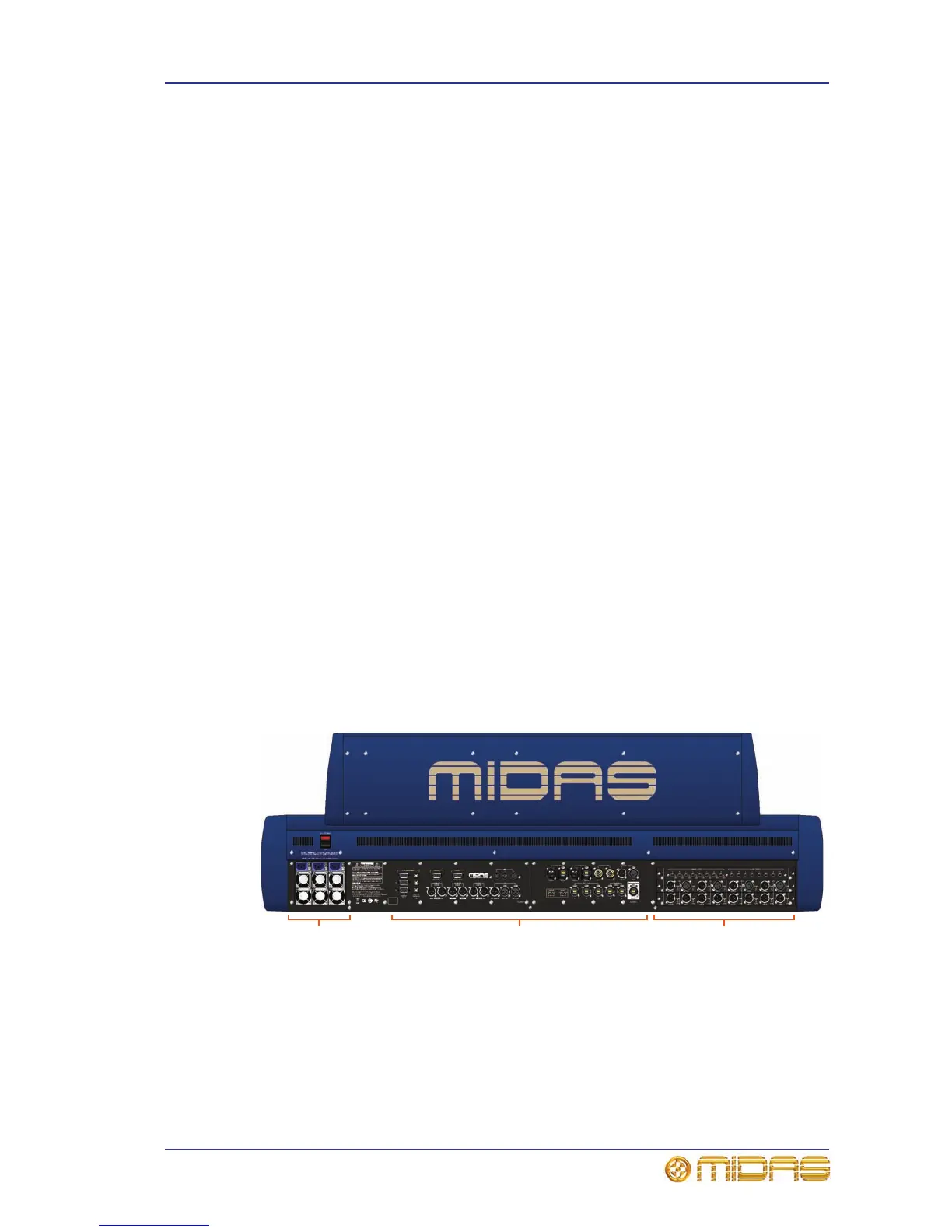
A connector panel on the rear of the control centre has three main sections (see below).
On the left are three mains power inlet and ventilation assemblies, with a
DC power switch above. The mid-section contains connections for the audio, network,
communications, intercoms, synchronisation, external remote devices and peripheral
devices. The section on the right is the user-configurable modular I/O section.
The modular I/O section can house up to three of any of the following I/O modules in
any combination: DL441 analogue input (mic) module; DL442 analogue output module;
DL443 analogue Jack I/O module; DL444 8 analogue mic in and 8 analogue line out
module and DL452 AES/EBU input and output module. This gives a maximum of 24
inputs and 24 outputs, if the appropriate cards are fitted.
Rear view of the control centre
For more information, see Chapter 29 "Panel Connections" on page 265.