4 Parts Replacement VJ-1604 Maintenance Manual
Rev.-05 4-34
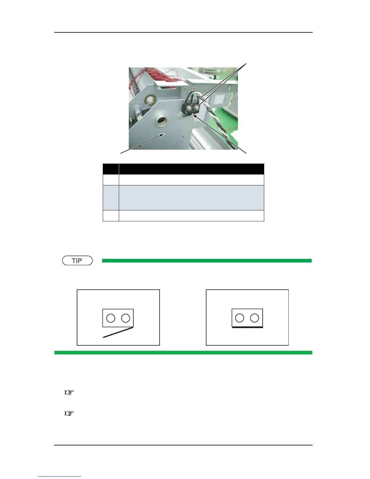
4. Remove the screws (2 pieces) that retain the cover sensor (C) assembly_R.
5. Remove the cover sensor (C) assembly_R.
6. To reassemble the unit, reverse the removal procedure.
The cover sensor looks like the following.
(2) L Side
1. Remove the side top cover L.
"4.2.7 Removing Side Top Cover L" p.4-14
2. Remove the switch cover L.
"4.2.13 Removing Switch Cover L" p.4-20
3. Detach the connector for the cover sensor (C) assembly_L.
No. Part name
1 Cover sensor (C) assembly_R
2 Screws that retain the cover sensor (C) assembly_R
(pan-head screw with spring washer and flat washer M2
×
12)
3 Damper cover R
2
1
3
Opened
Closed
 Loading...