Training Guide Course No. 196514
Level 2 Maintenance, X-1000 Series Dispensing Systems 4-93 P/N 196515 (Revision A)
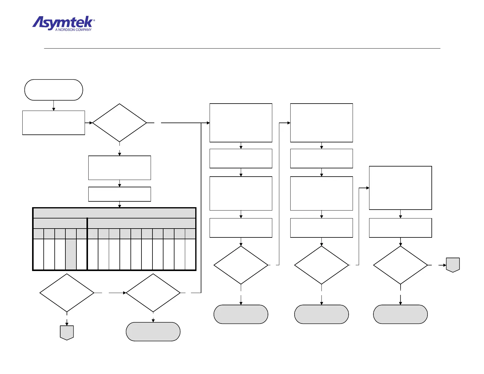
Are all
pneumatic system
devices inoperative
and yellow Beacon
light flashing?
Connect the Power Cable to
the facility outlet,
Main Air Solenoid (P/N 40-
2125) has failed.
Switch Main Circuit Breaker
to ON (I), press the green ON
(I) button on the Operator’s
Console and open FmNT.
From FmNT Main Window:
a. Select Tools.
b. Select I/O Test.
c. Select Conveyor.
Toggle the failed pneumatic
device. Refer to table below:
TABLE 1
Purge Cup
!A
Center Vacuum
1B
Left Vacuum
2A
Right Vacuum
2B
Left Stop Pin
3
Center Stop Pin
4
Center Lift Table
5
Right Stop Pin
6
Left Lift Table
7
Right Lift Table
8
X-1020
Purge Cup
Left Stop Pin
Center Stop Pin
Center Lift
1A2345
X-1010
Did the LED illuminate
on the Solenoid Valve?
Can tooling pressure
be adjusted to 40 psi?
Exit FmNT, shut down
Windows NT, press the black
OFF (0) button on the
Operator’s Console, switch
Main Circuit Breaker to OFF
(0), and disconnect Power
Cable from the facility outlet.
Remove Main Air Solenoid
Connector from J33 on XY
Servo Interface PWA.
Connect the Power Cable to
the facility outlet, switch Main
Circuit Breaker to ON (I)
position, press the green ON
(I) button on the Operator’s
Console, and enter FmNT.
Measure VDC on XY Servo
Interface PWA J33, Pin 1 and
Pin 2.
Is the reading 24
VDC?
Exit FmNT, shut down
Windows NT, press the black
OFF (0) button on the
Operator’s Console, switch
Main Circuit Breaker to OFF
(0), and disconnect Power
Cable from the facility outlet.
Remove Servo Interconnect
B Cable from J20 on XY
Servo Interface PWA.
Connect the Power Cable to
the facility outlet, switch Main
Circuit Breaker to ON (I)
position, press the green ON
(I) button on the Operator’s
Console, and enter FmNT.
Measure VDC on Servo
Interconnect B Cable P20,
Pin 22, and Pin 37.
Is the reading 5VDC?
Exit FmNT, shut down
Windows NT, press the black
OFF (0) button on the
Operator’s Console, switch
Main Circuit Breaker to OFF
(0) position, and disconnect
Power Cable from the facility
outlet.
Is there continuity?
Check continuity of Servo
Interconnect B Cable (Pinout
is 1 to 1).
XY Servo Interface PWA
(P/N 194036) has failed
Servo Interconnect B
Cable (P/N 06-4525-00)
has failed.
A
A
Solenoid Valve (P/N
197396 4-way or P/N
197397 Dual 3-way) has
failed
No
Yes
No
YesNo
Yes
No
Yes
No
Yes
No
Yes
Are all
pneumatic system
devices inoperative
and yellow Beacon
light flashing?
Are all
pneumatic system
devices inoperative
and yellow Beacon
light flashing?
Connect the Power Cable to
the facility outlet,
Main Air Solenoid (P/N 40-
2125) has failed.
Switch Main Circuit Breaker
to ON (I), press the green ON
(I) button on the Operator’s
Console and open FmNT.
From FmNT Main Window:
a. Select Tools.
b. Select I/O Test.
c. Select Conveyor.
Toggle the failed pneumatic
device. Refer to table below:
TABLE 1
Purge Cup
!A
Center Vacuum
1B
Left Vacuum
2A
Right Vacuum
2B
Left Stop Pin
3
Center Stop Pin
4
Center Lift Table
5
Right Stop Pin
6
Left Lift Table
7
Right Lift Table
8
X-1020
Purge Cup
Left Stop Pin
Center Stop Pin
Center Lift
1A2345
X-1010
TABLE 1
Purge Cup
!A
Center Vacuum
1B
Left Vacuum
2A
Right Vacuum
2B
Left Stop Pin
3
Center Stop Pin
4
Center Lift Table
5
Right Stop Pin
6
Left Lift Table
7
Right Lift Table
8
X-1020
Purge Cup
Left Stop Pin
Center Stop Pin
Center Lift
1A2345
X-1010
Did the LED illuminate
on the Solenoid Valve?
Did the LED illuminate
on the Solenoid Valve?
Can tooling pressure
be adjusted to 40 psi?
Can tooling pressure
be adjusted to 40 psi?
Exit FmNT, shut down
Windows NT, press the black
OFF (0) button on the
Operator’s Console, switch
Main Circuit Breaker to OFF
(0), and disconnect Power
Cable from the facility outlet.
Remove Main Air Solenoid
Connector from J33 on XY
Servo Interface PWA.
Connect the Power Cable to
the facility outlet, switch Main
Circuit Breaker to ON (I)
position, press the green ON
(I) button on the Operator’s
Console, and enter FmNT.
Measure VDC on XY Servo
Interface PWA J33, Pin 1 and
Pin 2.
Is the reading 24
VDC?
Is the reading 24
VDC?
Exit FmNT, shut down
Windows NT, press the black
OFF (0) button on the
Operator’s Console, switch
Main Circuit Breaker to OFF
(0), and disconnect Power
Cable from the facility outlet.
Remove Servo Interconnect
B Cable from J20 on XY
Servo Interface PWA.
Connect the Power Cable to
the facility outlet, switch Main
Circuit Breaker to ON (I)
position, press the green ON
(I) button on the Operator’s
Console, and enter FmNT.
Measure VDC on Servo
Interconnect B Cable P20,
Pin 22, and Pin 37.
Is the reading 5VDC?Is the reading 5VDC?
Exit FmNT, shut down
Windows NT, press the black
OFF (0) button on the
Operator’s Console, switch
Main Circuit Breaker to OFF
(0) position, and disconnect
Power Cable from the facility
outlet.
Is there continuity?Is there continuity?
Check continuity of Servo
Interconnect B Cable (Pinout
is 1 to 1).
XY Servo Interface PWA
(P/N 194036) has failed
Servo Interconnect B
Cable (P/N 06-4525-00)
has failed.
A
A
Solenoid Valve (P/N
197396 4-way or P/N
197397 Dual 3-way) has
failed
No
Yes
No
YesNo
Yes
No
Yes
No
Yes
No
Yes
Diagram Sheet 4-7-3
Pneumatics Fault Isolation Procedure - Pneumatics Verification

 Loading...


