Training Guide Course No. 196514
Level 2 Maintenance, X-1000 Series Dispensing Systems 4-115 P/N 196515 (Revision A)
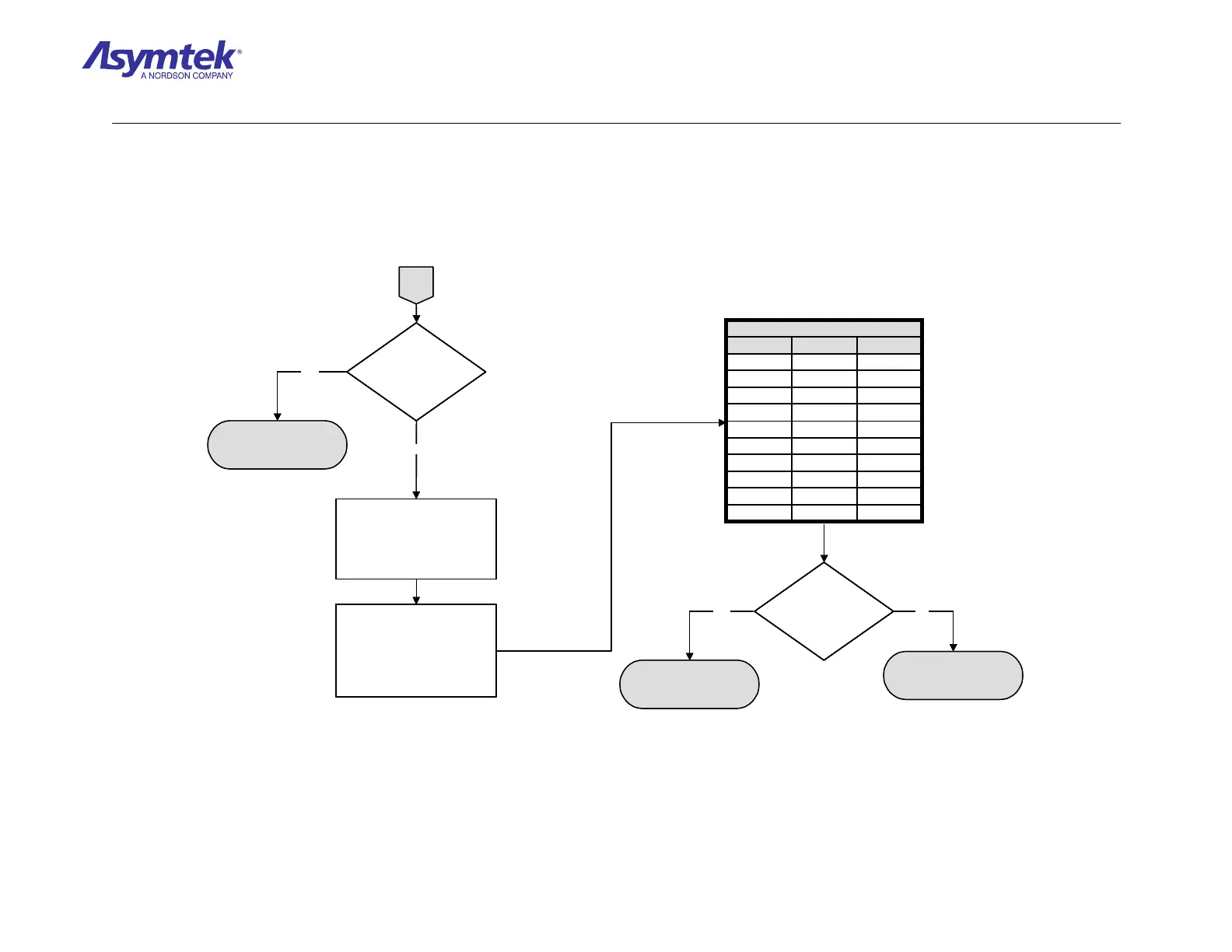
A
8ShieldShell
N/CPurple9
12Yellow8
11Orange7
2Blue6
1Brown5
4Green4
10Red3
3White2
9Black1
P2ColorP1
TABLE 2
Is there continuity?
SMEMA Upstream Cable
(P/N 06-4645-00) has
failed.
In FmNT I/O
SMEMA screen, verify
that “Board available
from upstream tool” is
displaying ON.
Exit FmNT, shut down Windows
NT, press black OFF (0) button
on the Operator’s Console,
switch Main Circuit Breaker to
OFF (0), and disconnect Power
Cable from facility outlet.
Verify continuity of P/N 06-4645-
00 SMEMA Upstream Cable,
routed between Conveyor
Controller and Rear Bulkhead of
dispensing system. Pin
connections are specified in
Table 2.
External SMEMA
Upstream Cable (P/N 06-
2142-00) has failed
Conveyor Controller
(P/N 62-1677-00 on
X1020, or P/N 62-1676 on
X1010) has failed.
Yes No
Yes
No
A
8ShieldShell
N/CPurple9
12Yellow8
11Orange7
2Blue6
1Brown5
4Green4
10Red3
3White2
9Black1
P2ColorP1
TABLE 2
8ShieldShell
N/CPurple9
12Yellow8
11Orange7
2Blue6
1Brown5
4Green4
10Red3
3White2
9Black1
P2ColorP1
TABLE 2
Is there continuity?Is there continuity?
SMEMA Upstream Cable
(P/N 06-4645-00) has
failed.
In FmNT I/O
SMEMA screen, verify
that “Board available
from upstream tool” is
displaying ON.
In FmNT I/O
SMEMA screen, verify
that “Board available
from upstream tool” is
displaying ON.
Exit FmNT, shut down Windows
NT, press black OFF (0) button
on the Operator’s Console,
switch Main Circuit Breaker to
OFF (0), and disconnect Power
Cable from facility outlet.
Verify continuity of P/N 06-4645-
00 SMEMA Upstream Cable,
routed between Conveyor
Controller and Rear Bulkhead of
dispensing system. Pin
connections are specified in
Table 2.
External SMEMA
Upstream Cable (P/N 06-
2142-00) has failed
Conveyor Controller
(P/N 62-1677-00 on
X1020, or P/N 62-1676 on
X1010) has failed.
Yes No
Yes
No
Diagram Sheet 4-8-16
SMEMA Fault Isolation Procedure – Upstream Workpiece Transfer Verification (Continued)

 Loading...


