1 Basic Operation
24
Using the Touchscreen
Touch a screen element to get to the actions linked to that element. For example, touch a
measurement numeric and the setup menu for that measurement opens. Touch a wave to enter the
setup menu for that wave.
Measurement Setup Menus
Each measurement has a setup menu where you can change settings. Typically, the setup menu
window covers the whole screen, except the INOP and alarm message fields, which are always
displayed at the top. The following picture is an example, and may not show exactly what you see on
the screen. All measurement setup windows are similar and share the same basic layout.
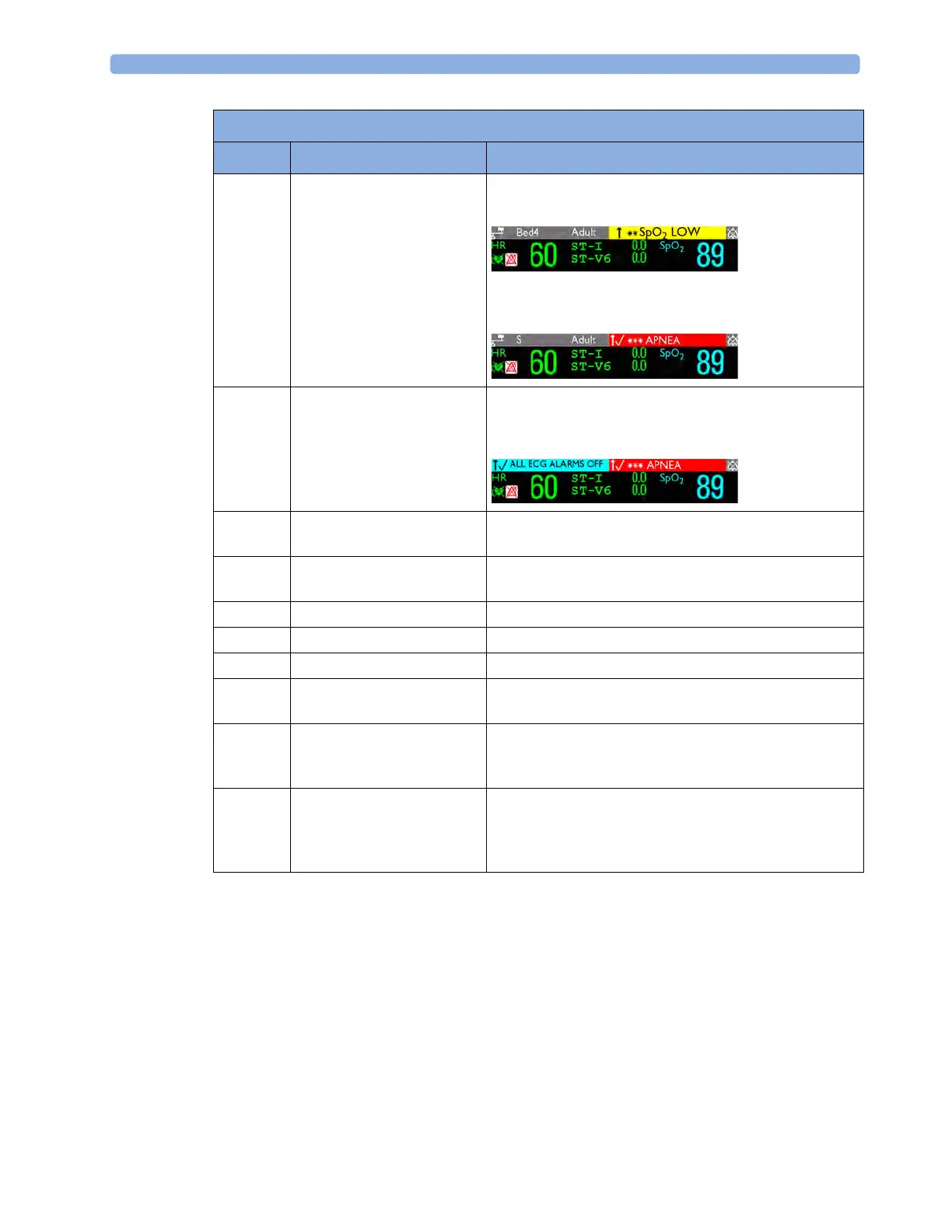
2 Patient name / alarm
message field
Patient name can be covered by alarm messages or alarms
On/Off/Paused message.
If red and yellow alarms are active at the same time, they
rotate in the alarm field.
3 Patient category and bed label
/ INOP message field
Patient category and bed label can be covered by INOP
messages. If there are multiple red/yellow/cyan INOPs
active at the same time, they rotate in the INOP field.
4 Network connection
indicator
Documented in Information Center Instructions for Use.
5 Measurement label Touch the measurement to enter the measurement setup
menu.
6 Paced status Displayed below the HR label.
7 Measurement numeric/values Touch the numeric to enter the measurement setup menu.
8 Measurement wave Touch the wave to enter the measurement setup menu.
9 Status line Shows information and messages prompting you for
action.
10 Measurement Selection key Opens the
Measurement Selection window which shows all
measurements and where they are physically located. From
here you can also enter the measurement setups.
11 Battery status indicator Gives information about remaining battery charge,
estimated operating time, maintenance requirements and
malfunctions. See the chapter “Using Batteries” on
page 249.
MP2 Screen Elements
Item Description Comments