Common Measurement Settings
R&S
®
FSVA3000/ R&S
®
FSV3000
308User Manual 1178.8520.02 ─ 01
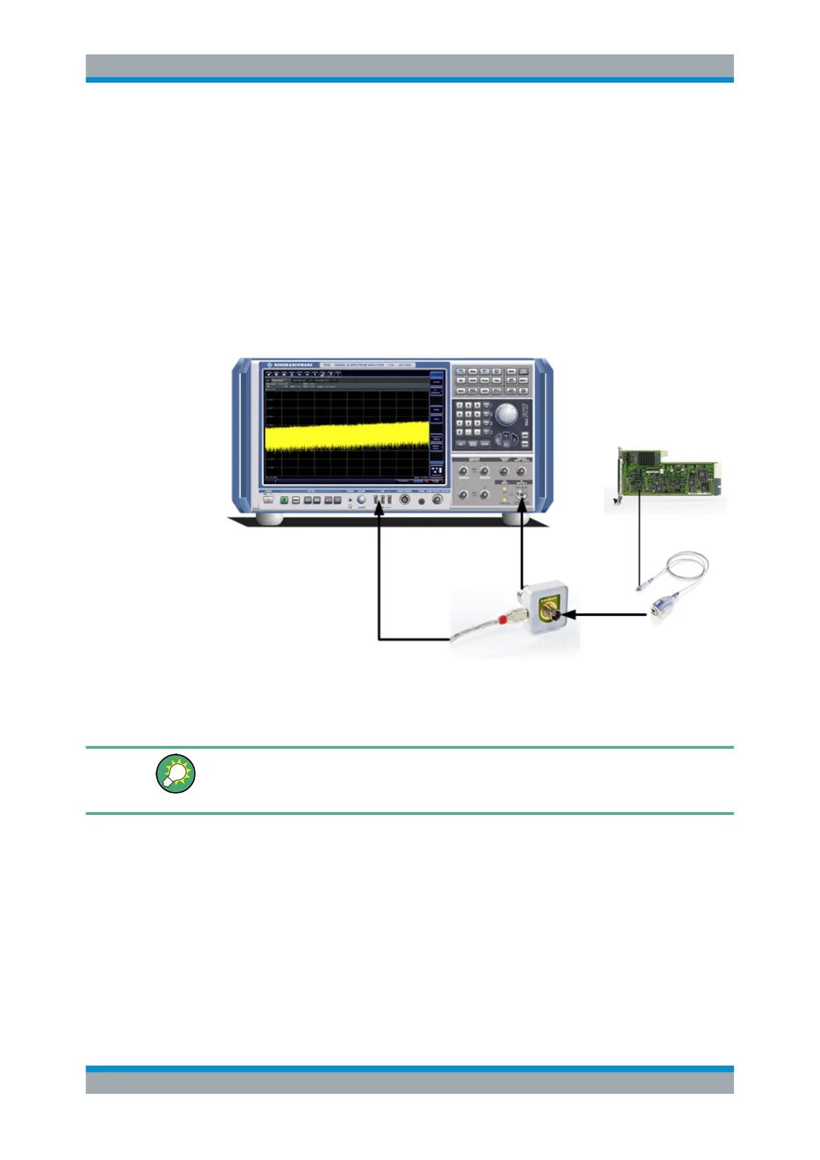
all active probes with a maximum bandwidth of up to 80 MHz, depending on the instal-
led bandwidth extension options. The R&S RT-ZA9 provides an interface between the
probe's BNC socket and the analyzer's N-socket. The USB connection provides the
necessary supply voltages for the probe.
To connect an active probe to the RF Input
1. Connect the R&S RT-ZA9 adapter to the RF Input connector on the R&S FSV/A.
2. Connect the R&S RT-ZA9 adapter's USB cable to a USB connector on the
R&S FSV/A.
3. Connect the probe to the adapter.
Probes are automatically detected when you plug them into the R&S FSV/A. The
detected information on the probe is displayed in the "Probes" tab of the "Input"
dialog box.
To determine whether the probe has been connected properly and recognized by the
R&S FSV/A, use the [SENSe:]PROBe<pb>:SETup:STATe? remote control com-
mand.
Impedance and attenuation
The measured signal from the probe is attenuated internally by the probe's specific
attenuation. For RF probes, the attenuation is compensated using a pre-defined "Probe
on RF Input" transducer factor, which is automatically activated before the common RF
data processing. The reference level is adjusted automatically.
A fixed impedance of 50 Ω is used for all probes to convert voltage values to power
levels.
Data Input and Output

 Loading...


