Design Guidelines
Transport System Design
112 MagneMotion
Rockwell Automation Publication MMI-UM002F-EN-P - October 2022
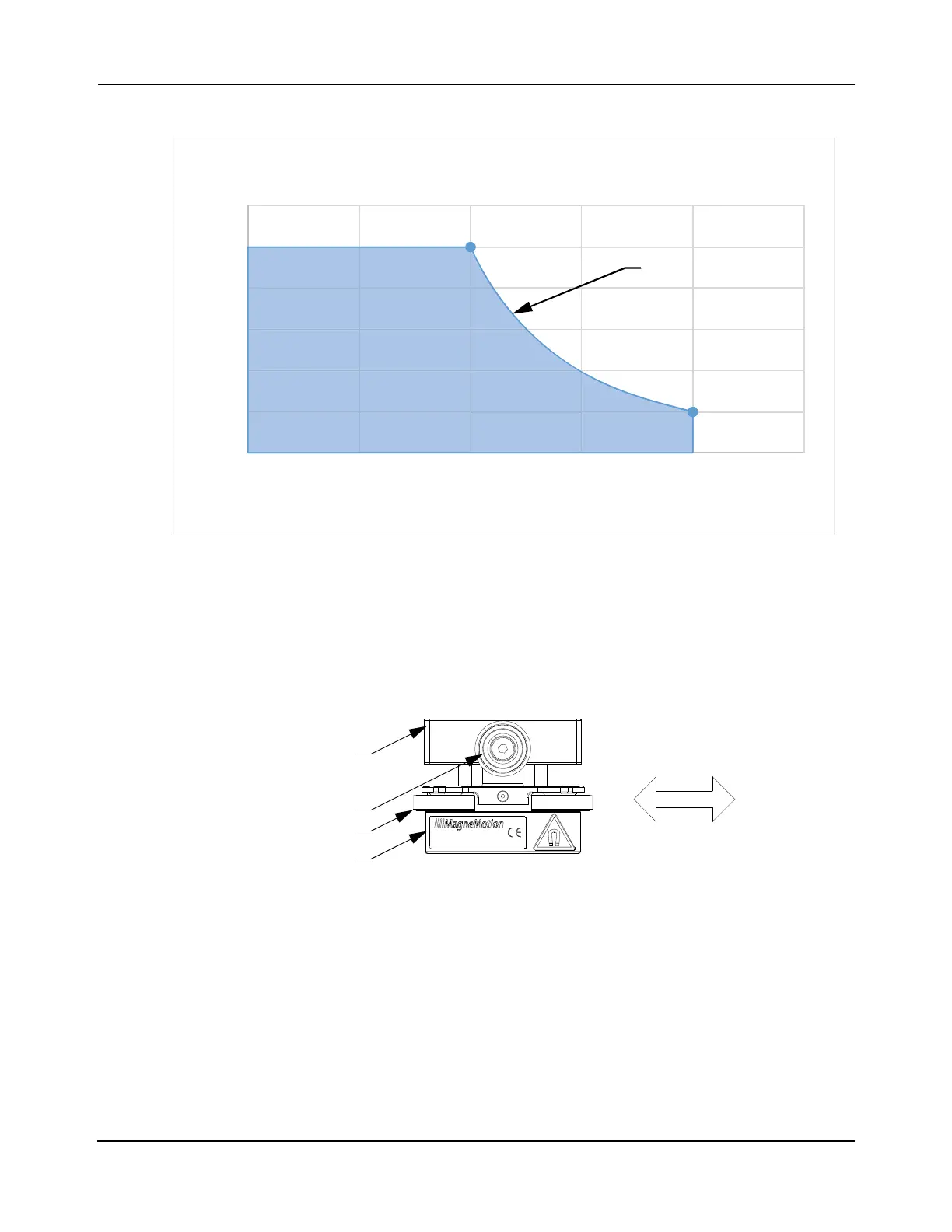
Figure 3-37: Dual Array (Tandem) Wheeled Puck Payload vs. Velocity
The 2-wheel puck with one magnet array, which is shown in Figure 3-38, is used in the tan-
dem puck as shown in Figure 3-35. These pucks are available separately for use with user
designed linkage plates to create custom tandem pucks. They must be used in a tandem con-
figuration to keep the puck from pivoting around the axle, which helps prevent the magnet
array from impacting the motor.
Figure 3-38: Single Array 2 Wheel Puck
0
2
4
6
8
10
12
0 0.5 1 1.5 2 2.5
Payload (kg)
Velocity (m/s)
Dual Array (Tandem) Wheeled Puck Max Velocity
High Payload Switch
Curve Motors
Puck Body
Suspension Wheels
Magnet Array
Lateral Guide Wheels
 Loading...


