Installation
Option Installation
MagneMover LITE User Manual 287
Rockwell Automation Publication MMI-UM002F-EN-P - October 2022
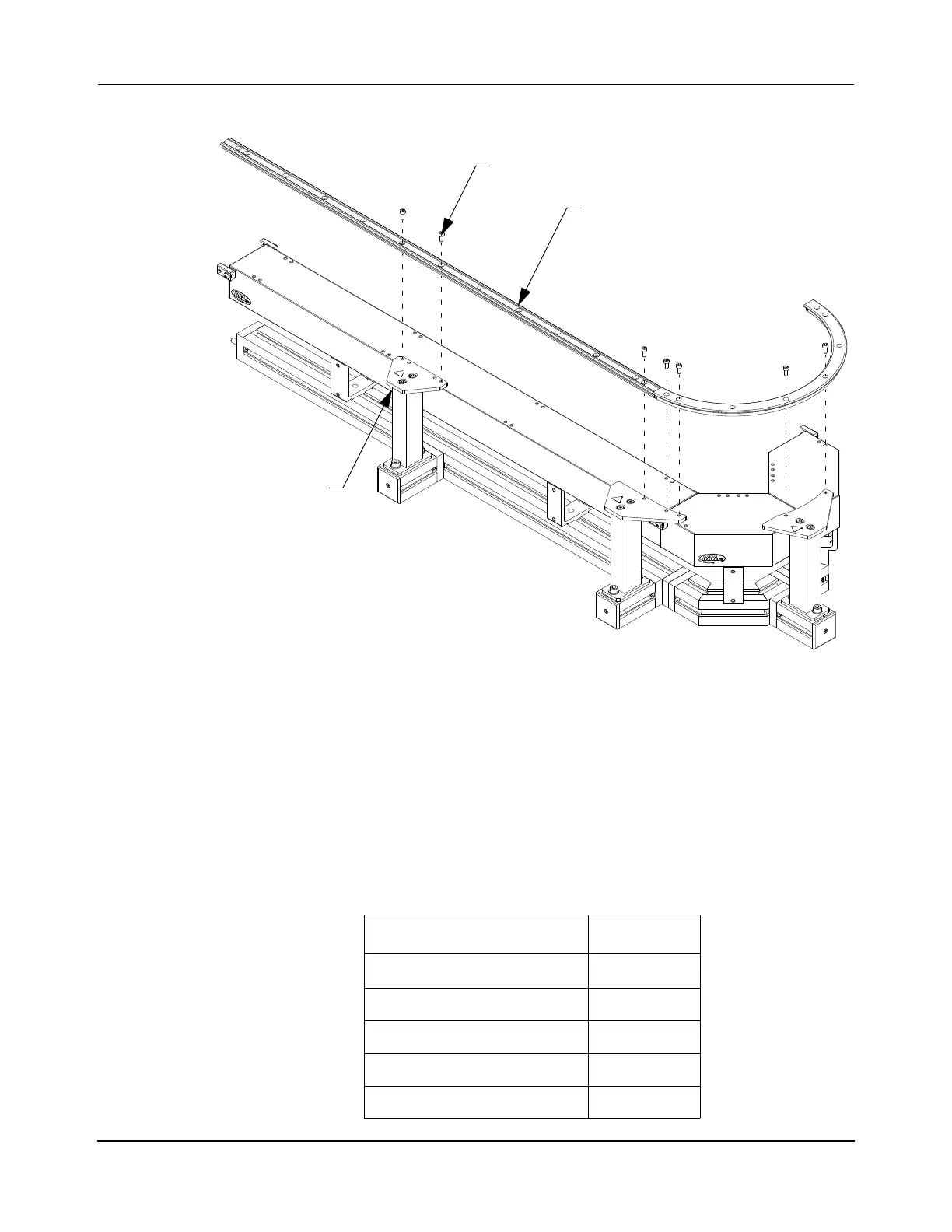
Figure 5-34: Attaching Precision Rail to Spine Plates
4. Adjust the position of the support post assemblies as required.
5. Loosely secure the rails to the corresponding spine plates using M5 SHC screws. Fin-
ger-tighten then back off one-half turn to provide the parts a small amount of move-
ment relative to each other to allow adjustment.
The number of screws that are required for each spine plate attachment is identified in
Table 5-4.
Table 5-4: Precision Rail to Spine Plate Attachment Screws
Spine Plate Type Screws
Joint, Straight-to-Straight 2
Joint, Straight-to-Curve 3
Joint, Curve-to-Curve 4
No Joint, Straight 2
No Joint, Curve 2
Spine Plate
M5 Screw
Precision Rail
(typical)
 Loading...


