Installation
Transport System Installation
MagneMover LITE User Manual 267
Rockwell Automation Publication MMI-UM002F-EN-P - October 2022
RS-422 Motor Communication
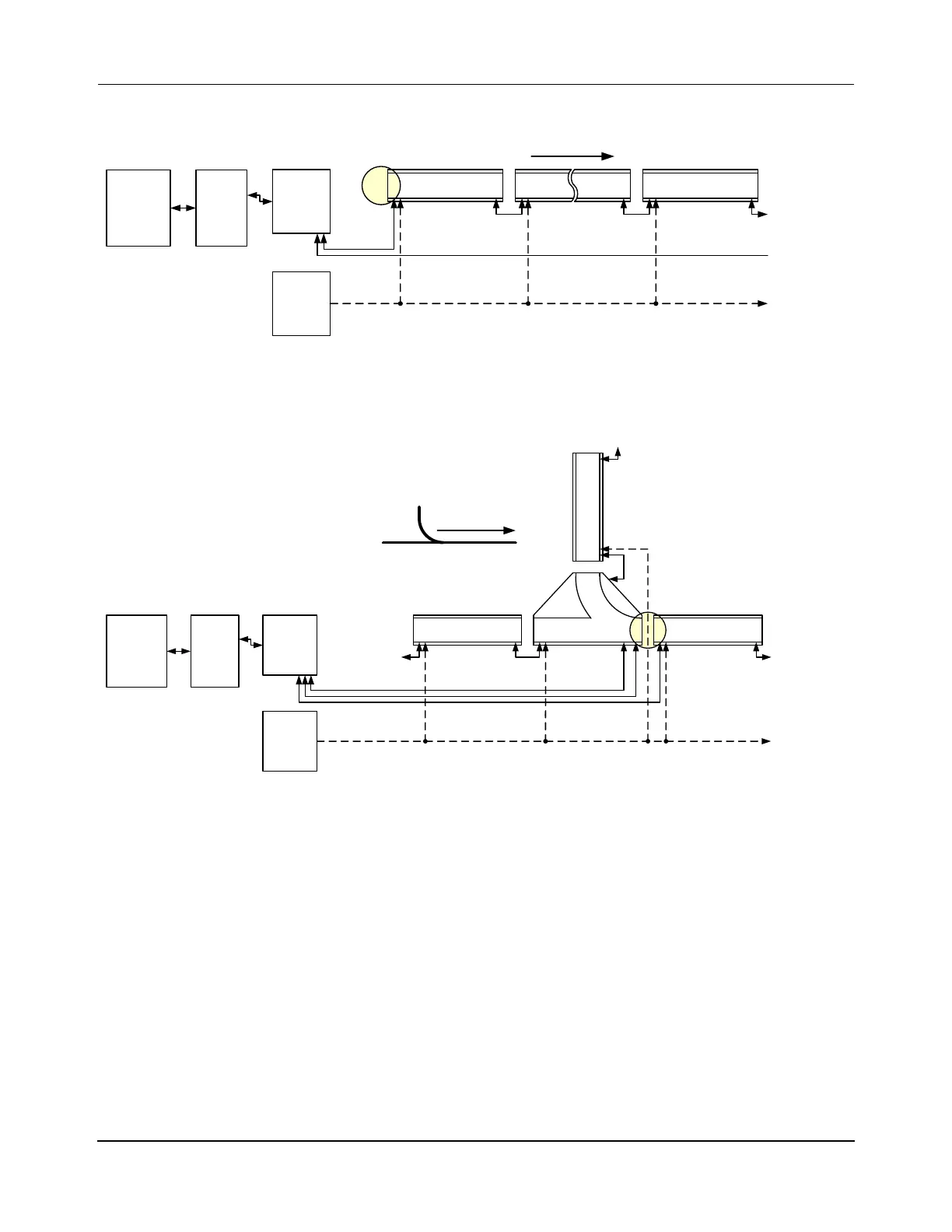
Figure 5-18: Simplified Representation of RS-422 Motor Connections
Figure 5-19: Simplified Representation of RS-422 Merge Switch Connections
Installing RS-422 Motor Communication Cables
See Figure 4-56 on page 208 and Figure 4-58 on page 213 for the RS-422 communication
connection locations on the motors and switches. See the Node Controller Hardware User
Manual, MMI-UM013, for the communication connection locations on the node controllers.
See Figure 5-18 and Figure 5-19 for simplified diagrams of the wiring and Figure 5-20 for a
detailed example. The connections for a diverge switch are different than the connection
shown in Figure 5-19 for a merge switch.
When connecting the motors to the node controllers, both ends of a path do not need to con-
nect to the same node controller. However, all connections to the motors at the ends of all
paths that meet in a node must be made to the same node controller. See the MagneMover
LITE Configurator User Manual, MMI-UM008, for more information about nodes and paths.
Simple
Node
RS-422 Motor
(Straight or Curve)
Host
Controller
Ethernet
Switch
HLC &
Node
Controller
Power
Supply
Power
To Next
Motor in Path
Upstream Downstream
To Next
Motor in Path
From Last
Motor in Path
RS-422
Downstream
RS-422 Motor
(Straight or Curve)
Merge
Node
Host
Controller
Ethernet
Switch
HLC &
Node
Controller
Power
Supply
Power
RS-422
RS-422 Switch
Upstream Downs tream
From Previous
Motor in Path
Upstream
To Next Motor
in Path
From Previous
Motor in Path
Switch Configuration
Downstream
To Next
Motor in Path
RS-422 Motor
(Straight or Curve)
RS-422 Motor
(Straight or Curve)
RS-422 Motor
(Straight or Curve)
 Loading...


