Design Guidelines
Transport System Design
MagneMover LITE User Manual 95
Rockwell Automation Publication MMI-UM002F-EN-P - October 2022
Using Both RS-422 and Ethernet Motors
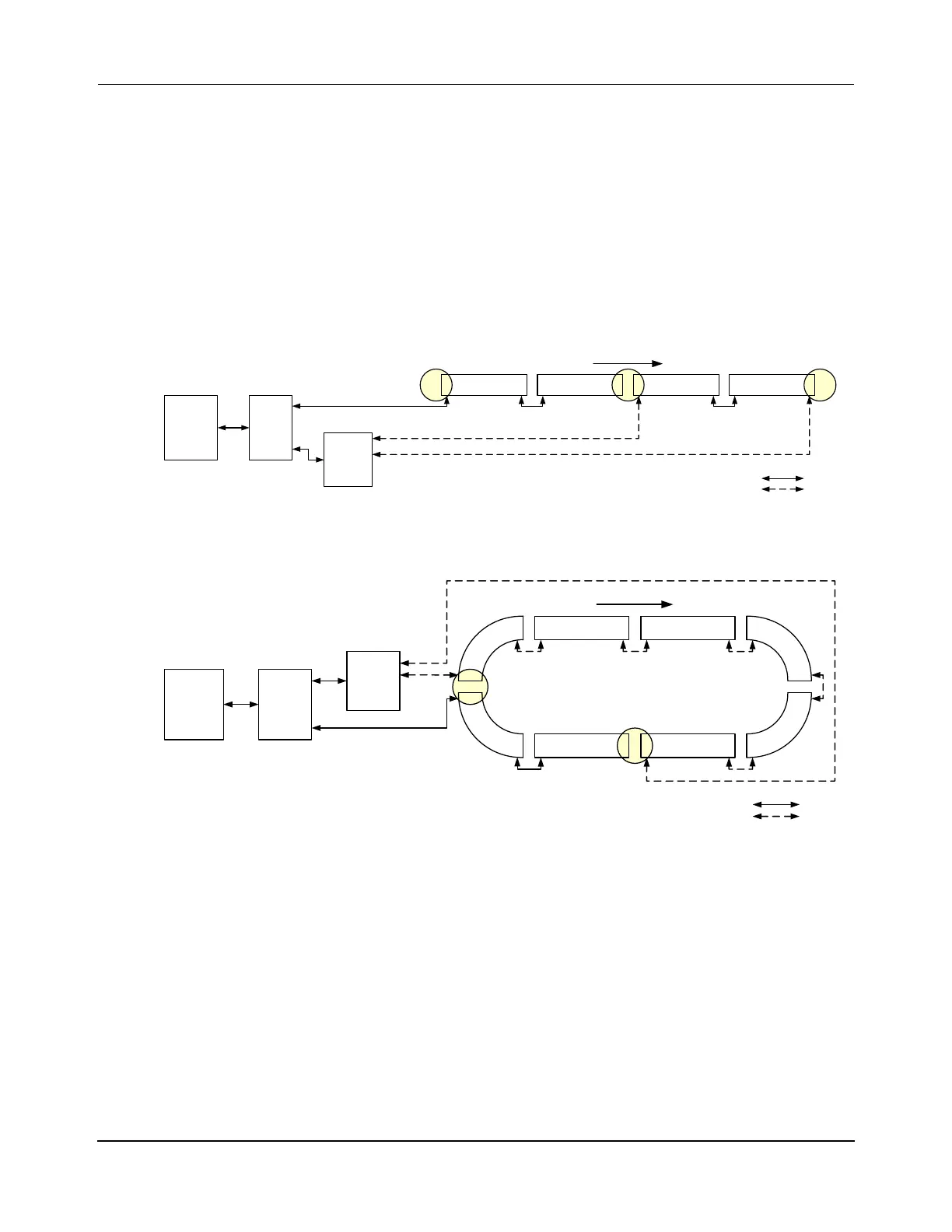
Transport systems can easily combine both RS-422 and Ethernet motors. Motor types are typ-
ically combined in a transport system when new Ethernet motors are added to an existing
RS-422 system. When adding new motors that use Ethernet for communication, it is recom-
mended that they be added as one path to simplify configuration. Nodes are needed at the
junction of RS-422 and Ethernet paths as shown in Figure 3-20, Figure 3-21, and Figure 3-22
to make the transition between motor types. Additionally, all Ethernet motors and their loca-
tion on the path must be defined in the MICS file (see Ethernet Motor MICS File on page 97).
Straight Paths
Figure 3-20: Ethernet Motor Wiring – Two Paths, Ethernet Chain and RS-422 Chain
Loop Paths
Figure 3-21: Ethernet Motor Wiring – Two Paths, Ethernet Chain and RS-422 Chain
Term
Node
Simple
Node
Relay
Node
Enet Motor
Host
Controller
Enet Motor RS-422 Motor RS-422 Motor
Enet
Switch
Straight Transport System (Recommended):
Mixed Enet and RS-422 motors, Two Paths, Split Chain
One Enet Chain, One RS-422 Chain
Ethernet
RS-422
RS-422
x.y.0.10
P1M1
x.y.1.1
P1M2
x.y.1.2
P2M1
P2M2
Ethernet
Downstream
HLC &
Node
Controller
RS-422
Ethernet
P2M1
x.y.2.1
P2M2
x.y.2.2
HLC &
Node
Controller
Host
Controller
Relay
Node
RS-422 Motor RS-422 Motor
P1M1
P1M2 P1M3
P1M4
P1M5
P1M6
RS-422
Motor
Enet
Motor
RS-422
Motor
RS-422
Motor
Relay
Node
Enet
Switch
Enet Motor RS-422 Motor
Loop Transport System:
Mixed Enet and RS-422 motors, Two Paths
One Enet Chain, One RS-422 Chain
Ethernet
RS-422
Downstream
RS-422
Ethernet
 Loading...


