Installation
Transport System Installation
MagneMover LITE User Manual 259
Rockwell Automation Publication MMI-UM002F-EN-P - October 2022
3. Using fingers, align the rails at the motor joints as shown in Figure 5-12. Tighten the
two M6 x 12 mm screws on each V-brace at that motor joint to 3.4 N•m [30 in•lb] with
a T30 Torx bit.
4. Tighten the M6 bolt to 5.5 N•m [49 in•lb] with a 10 mm Hex socket to secure the
motor to the motor mount.
For stainless steel rails the Loctite must cure for 2 hours at 22° C [72° F] before using
the transport system.
5. Repeat Step 3 at all motor joints.
6. Repeat Step 4 at all motors.
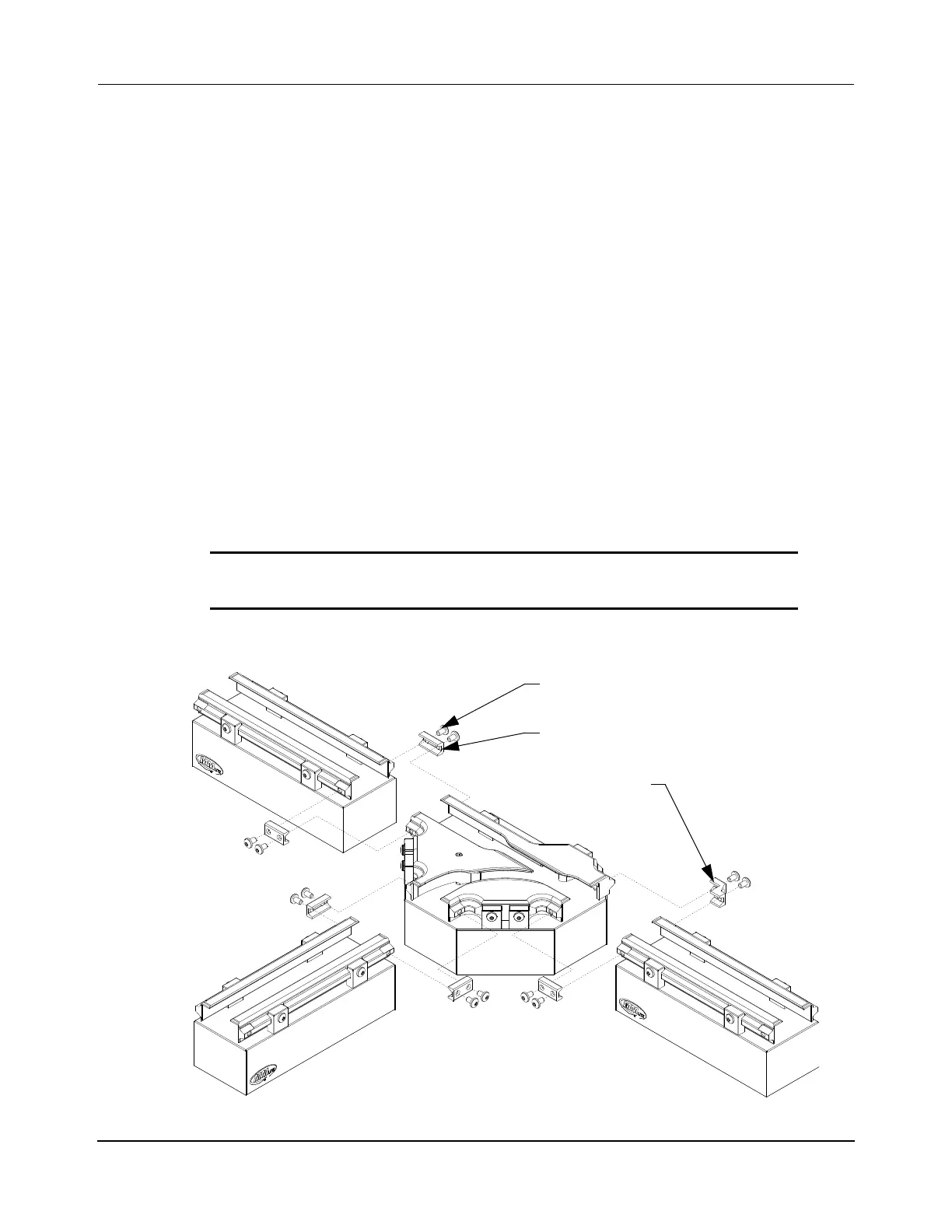
Switch Alignment
When aligning and securing the ends of the rails on the motors to the ends of the rails on the
switches, a V-brace is attached over the alignment features on all rails on each switch. For cer-
tain connections extended v-braces are required, see Figure 5-13 and Figure 5-14. Use stan-
dard v-braces (200-2002-xx) for all other rail connections.
Figure 5-13: Install Standard Switch
IMPORTANT Moving the rails on the switches can affect the operation of
the switch and requires recalibration of the switch.
Switch V-brace
(200-2078-XX)
Standard V-brace
(5X 200-2002-XX)
M6 x 12 mm Screw
(2X per V-brace)
 Loading...


