Design Guidelines
Transport System Design
84 MagneMotion
Rockwell Automation Publication MMI-UM002F-EN-P - October 2022
• Motor Gap (physical distance between motors) and downstream gap (actual distance
between motor blocks in adjacent motors), see Figure 3-7. The use of custom motor
mounts that change the default space between motors is not recommended.
The effect of the first two variables, the number of cycles of magnet array and the vehicle gap
cannot be changed.
At the nominal vehicle gap between the magnet array and the top of the MagneMover LITE
motor, the motors provide approximately 6 N [1.3 lbf] thrust per magnet array (see Table 3-3)
during continuous use. This gap is 1 mm [0.04 in] for G3 magnet arrays and 1.5 mm [0.06 in]
for G4.2 and later magnet arrays.
The magnet array comes in one length (1 cycle), however two arrays can be used in a dual
array vehicle (see Pucks on page 105), which effectively doubles the length of the magnet
array and doubles the thrust.
Required Thrust
Several variables determine the thrust required to move a vehicle (puck):
• Required acceleration.
• Mass to be moved.
• Friction or drag between the vehicle and the guideway.
Motor Gap
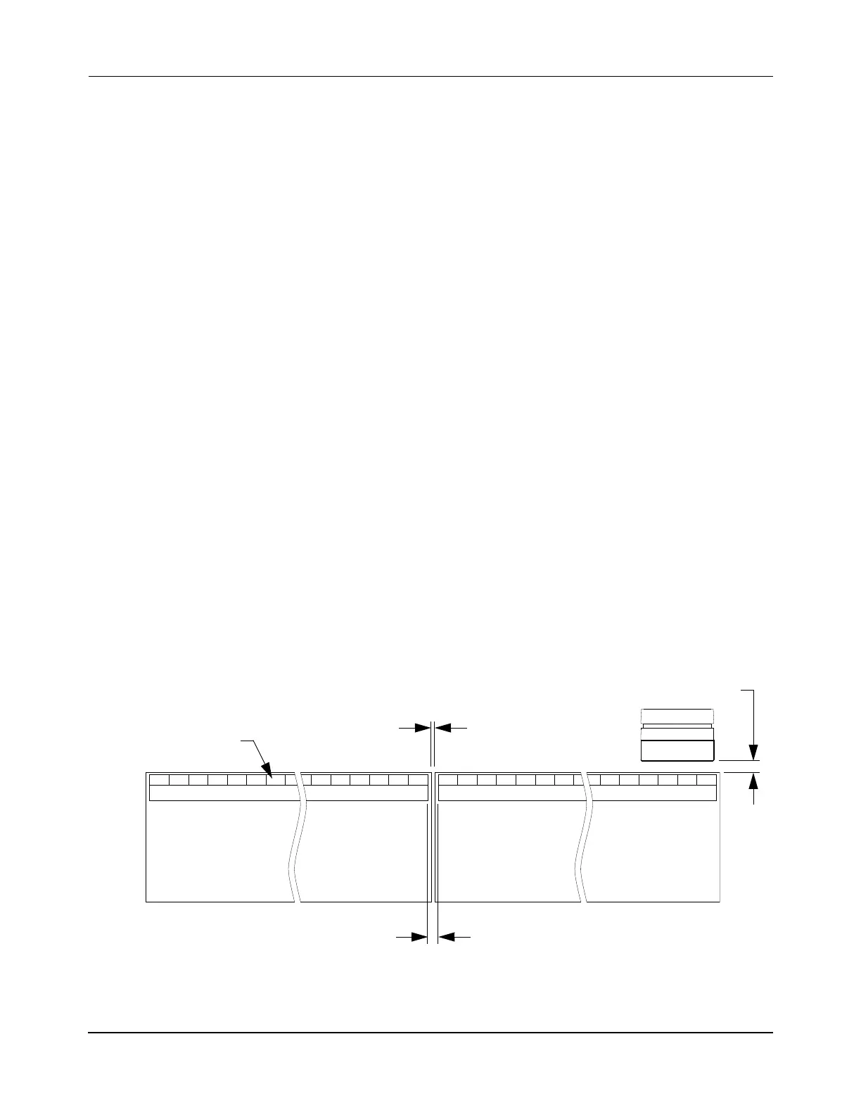
For MagneMover LITE motors installed in a transport system, there is always a space (Motor
Gap) between motors, as shown in Figure 3-7. The required Motor Gap is 1 mm, which places
1 m MM LITE motors on a 1 meter pitch.
Figure 3-7: MagneMover LITE Motor Gaps
Motor Gap (1 mm)
Downstream Gap
MagneMover LITE Motor
Motor Block
Vehicle Gap
(Motor Gap + 2 mm)
(side view)
 Loading...


