Installation
Option Installation
286 MagneMotion
Rockwell Automation Publication MMI-UM002F-EN-P - October 2022
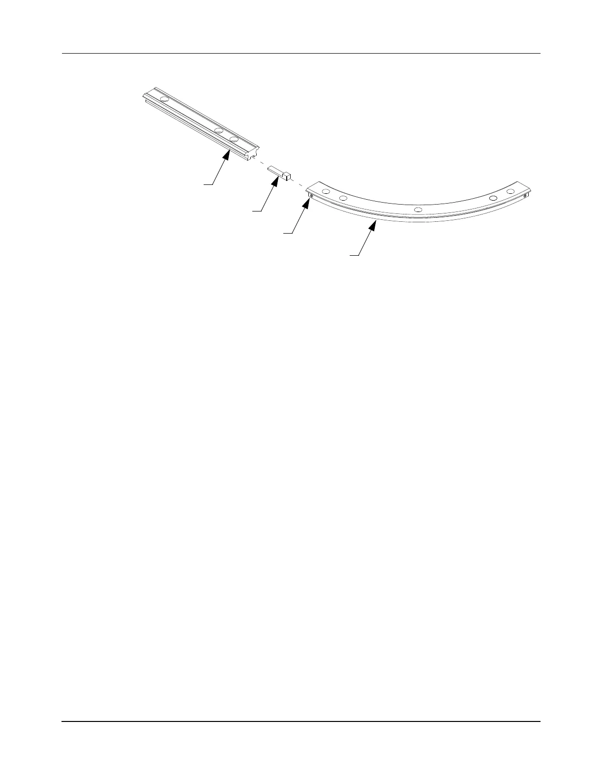
Figure 5-33: Attaching Straight Precision Rails to Curved Rails with Adjustment Key
A. Back-out the jacking screws on both sides of the curved rail.
B. Insert the large end of the adjustment key into the end of the curved rail and
tighten the jacking screws enough to hold it in place.
C. Insert the thin end of the adjustment key into the end of the straight rail.
D. Loosen the jacking screw on one side of the rail and tighten the jacking screw
on the other side of the rail to align the two rail section.
3. Position the rails over the edge of the spine plates, aligning the mounting holes in the
rail over the spine plate holes as shown in Figure 5-34.
NOTE: During rail adjustment and alignment, the spine plates must be loosely
attached to the support post assembly to provide the parts a small amount of
movement relative to each other to allow adjustment.
Before attaching the final rail within a closed loop system, install all vehicles
onto the rails. See Replace Precision Rail Vehicles on page 428.
Straight Rail
Jacking Screw
Curved Rail
Adjustment Key
 Loading...


