Specifications and Site Requirements
Electrical Specifications
218 MagneMotion
Rockwell Automation Publication MMI-UM002F-EN-P - October 2022
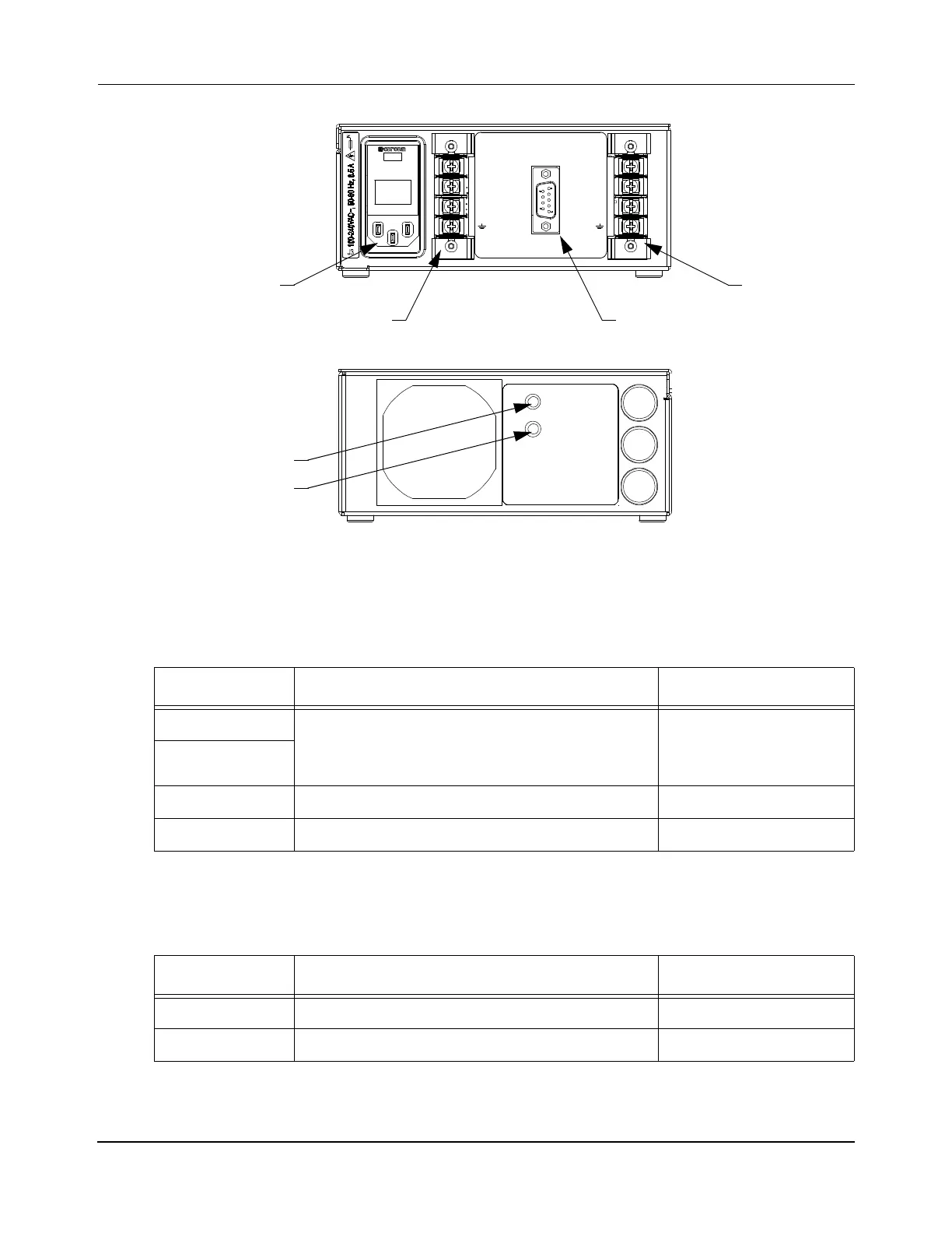
Figure 4-60: MM LITE Power Supply Electrical Connections and Indicators
Table 4-25: MM LITE Power Supply Electrical Connections
Label Description Connector Type
J1 Motor power
• V+ Propulsion – +36V DC ±1%, 300 W
• V+ Logic – +36V DC ±1%
Screw terminals
J2
J3 100…240V AC~, 50…60 Hz, 8.5 A IEC 320, Plug
J4 DC Enable DE-9, Socket
Table 4-26: MM LITE Power Supply Indicators
Label Description Indicator Type
LOGIC ON – Indicates that motor logic power is on. Green Light
PROPULSION ON – Indicates that motor propulsion power is on. Green Light
GND
J4 DC ENABLE
(SEE MANUAL FOR PINOUT)
36 VDC
300W / 8A MAX
36 VDC
300W / 8A MAX
J1 J2
GND
V+
PROPULSION
V+
LOGIC
V-
RETURN
V+
LOGIC
V-
RETURN
V+
PROPULSION
AC Power
DC Enable
Motor Power
Motor Power
Front View
F3
LOGIC
T, 250 V, 1 0 A
F1
PROPULSION 1
T, 250 V, 1 0 A
LOGIC
PROPULSION
F2
PROPULSION 2
T, 250 V, 1 0 A
SEE MANUAL FOR FILTER MAINTENANCE
LOGIC
Rear View
PROPULSION
J3
J1
J2
J4
 Loading...


