Specifications and Site Requirements
Electrical Specifications
MagneMover LITE User Manual 213
Rockwell Automation Publication MMI-UM002F-EN-P - October 2022
Switches
See 90° Left Switches on page 172 and 90° Right Switches on page 175 for mechanical draw-
ings.
NOTE: The switches draw an additional 15 W of power per vehicle (puck) when the vehicle
is moving at maximum acceleration or velocity (see Table 4-9).
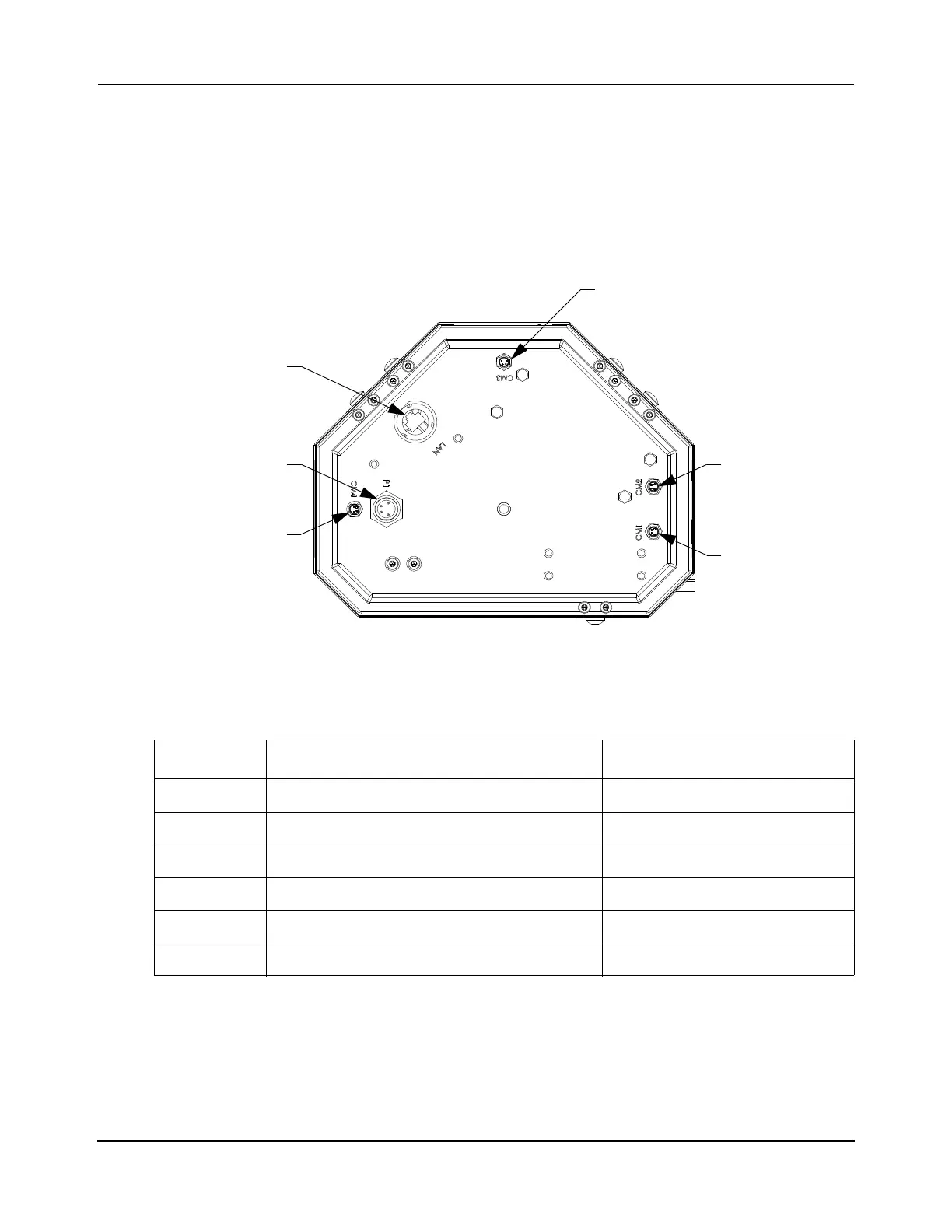
Figure 4-58: MagneMover LITE RS-422 Switch Electrical Connections
Table 4-18: MagneMover LITE RS-422 Switch Electrical Connections
Label Description Connector Type
CM1 RS-422 communication M8 Nano-Mizer, 4-Pin, Plug
CM2 RS-422 communication M8 Nano-Mizer, 4-Pin, Plug
CM3 RS-422 communication M8 Nano-Mizer, 4-Pin, Plug
CM4 RS-422 communication M8 Nano-Mizer, 4-Pin, Plug
P1 +36V DC ±10%, 1.5 A typical, 5.0 A max Mini-Conn-X, 4-Pin, Plug
LAN Ethernet – 10/100/1000 Base-Tx RJ45, Socket, IP-67
Power
Curve Section
Bottom View (Left Switch Shown)
RS-422 Connector
Straight Section
RS-422
Connector
Connector
Curve Section
RS-422
Connector
Straight Section
RS-422
Connector
Ethernet
Connector
 Loading...


