Design Guidelines
Transport System Options
MagneMover LITE User Manual 137
Rockwell Automation Publication MMI-UM002F-EN-P - October 2022
Precision Locator Installation
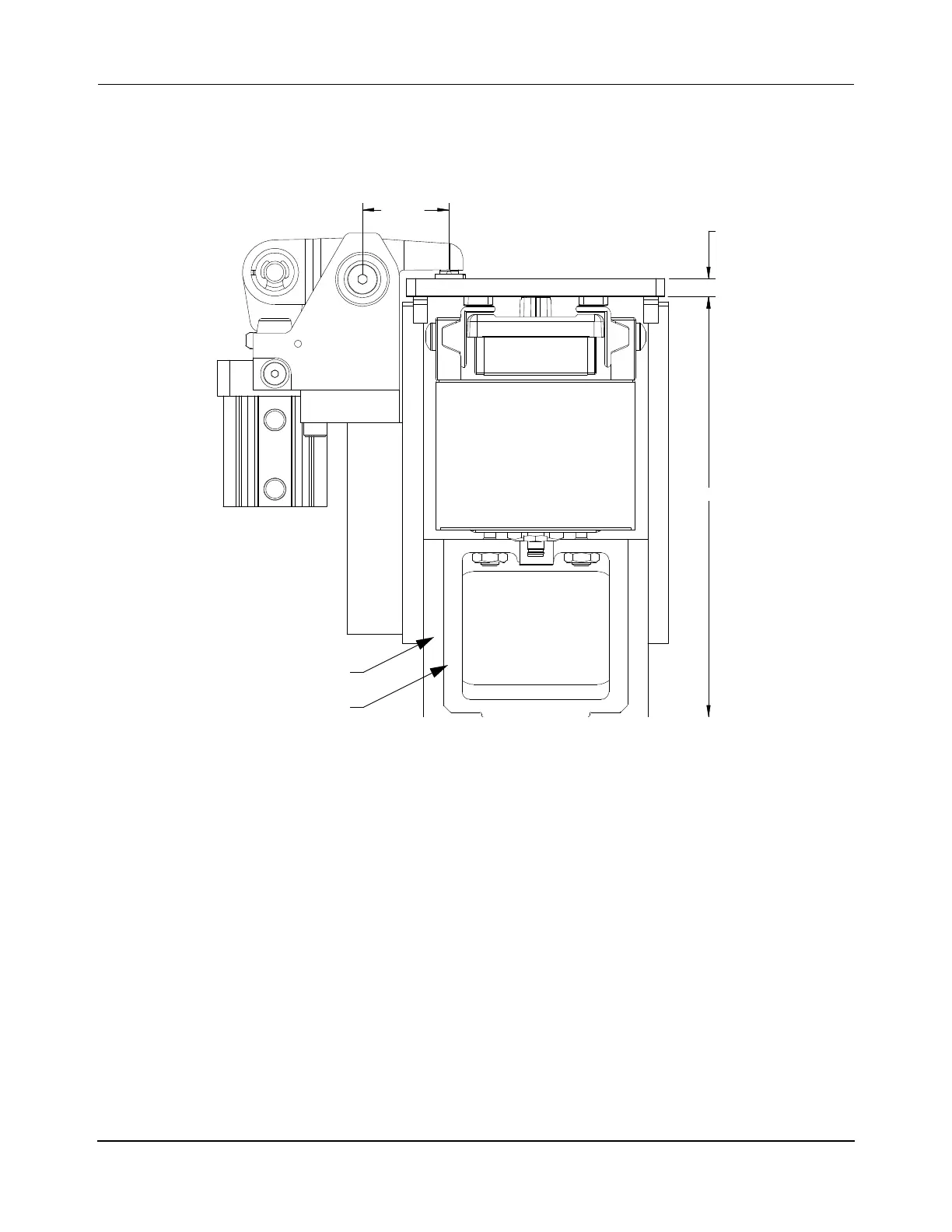
The precision locator is installed using the locator stand. Figure 3-62 shows the critical
dimensions for the installation.
Figure 3-62: Precision Locator Installation Dimensions
Once the precision locator is installed, the location for the pallet at the precision locator sta-
tion must be taught to make sure that the locator properly secures the pallet. Then, the location
of the pallet while it is secured must be taught to the interfacing equipment.
NOTE: Replacement of the locator stand can require reteaching of the pallet location.
Pneumatic Piping
The precision locator is designed to operate at a nominal 2.03 cc
3
/sec @ 0.41 mPa
[0.0043 scfm @ 60 psi] per cycle @ 21° C [70° F] @ sea level. The compressed air system
and the piping to the locators must be designed to support this requirement. A pneumatic
block diagram for the precision locator that uses a 5/2 valve is provided in Figure 3-63. Oper-
ation of the valve is described after the figure.
182.1
FIXTURE PLATE
THICKNESS
8MM (5/16")
2X 37.5
Locator Stand
Adjustable Motor Mount
 Loading...


