Installation
Transport System Installation
256 MagneMotion
Rockwell Automation Publication MMI-UM002F-EN-P - October 2022
Mounting Motors and Switches
All motors and switches, with their motor mounts attached, must be attached to the beam sec-
tions. Starting at one end of the system, install all switches then fill the space between the
switches with the motors.
NOTE: If precision locators are being used, install the locator stands before installing the
motors at those locations (see Precision Locator Installation on page 296).
If motors or switches are being mounted to supports other than the MagneMover
LITE stand system, make sure that the motors are flat and level once assembled.
When using motors with integral rails, before installing all motors in a closed system
add the pucks by sliding them onto the end of a motor that has been installed.
Do not remove any of the rails from the switches.
Make sure that all motors on parallel paths are parallel.
Mounting the motors is the same for motors with rails and for railless motors.
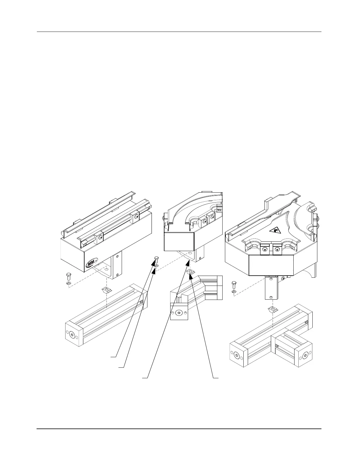
Figure 5-10: Installing Motors and Switches
1. Insert an M8 T-nut in the top channel of the beam at the approximate location for each
motor mount, see Table 5-2 for quantities and locations. T-nuts must be inserted so that
the spring steel tabs are facing toward the beam, then rotated clockwise into place.
Locating Boss
M8 x 20 mm Bolt
M8 Lock Washer
M8 T-Nut
Straight Motors (typical) Curve Motors (typical)
Switches (typical)
 Loading...


