Installation
Option Installation
MagneMover LITE User Manual 285
Rockwell Automation Publication MMI-UM002F-EN-P - October 2022
Attach Rails to Spine Plates
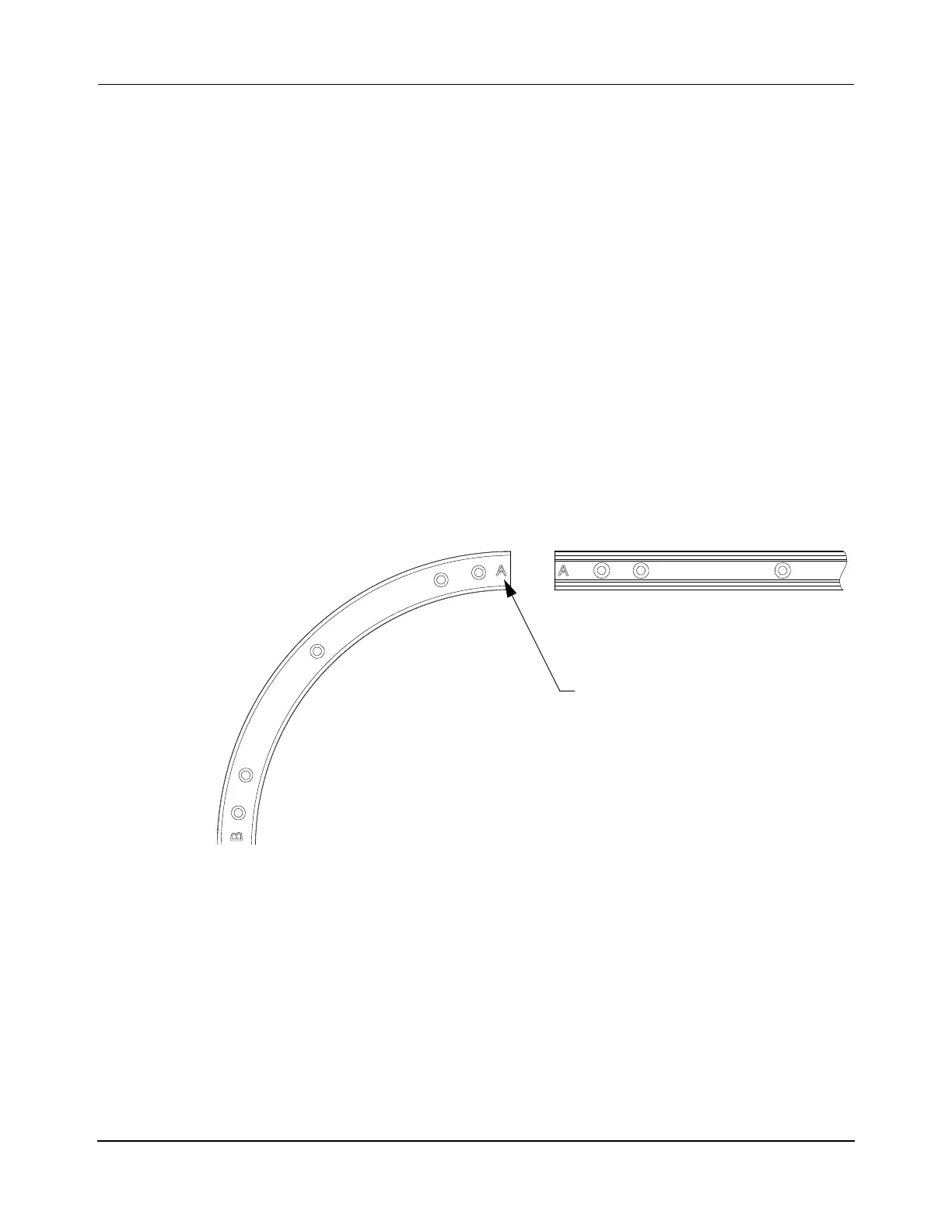
The precision rails are provided as a matched set with adjoining rail ends lettered (engraved)
at the factory as A to A, B to B, C to C, and so on, as shown in Figure 5-32. Rails typically
attach to spine plates at a joint where the ends of two rails meet, as shown in Figure 5-33.
However, some rails can attach to spine plates along the mid-point of a rail, as shown in
Figure 5-34.
NOTE: Before attaching and securing the final rail within the system, install all vehicles
onto the rails by sliding them onto an open section of rail (see Replace Precision
Rail Vehicles on page 428).
Make sure that all rails on parallel paths are parallel.
1. Identify the letters engraved on the end of each rail segment (see Figure 5-32) and lay-
out the rails so matching letters (A to A, B to B, C to C, and so on) align.
NOTE: When a rail segment is not used or is mislocated, the letters between the
joints do not match. In this case, during alignment and adjustment the ends of
the mismatched rails must be honed to achieve the proper alignment and per-
formance.
Figure 5-32: Precision Rail End Identification
2. When connecting a straight rail section to a curved rail section, an adjustment key is
used to make sure of proper alignment between the sections as shown in Figure 5-33.
NOTE: The adjustment key is inserted for connecting straight rail to curved rail sec-
tions only. The adjustment key is not required for other rail to rail connec-
tions.
 Loading...


