Operation
Theory of Operation
MagneMover LITE User Manual 317
Rockwell Automation Publication MMI-UM002F-EN-P - October 2022
A summary of MagneMover LITE transport system benefits includes:
• Less maintenance than conventional belt conveyors.
• No moving parts within the straight and curve motor modules.
• Passive vehicles (pucks) that do not require batteries, wires, or power.
• Bidirectional movement.
• Variable transport system layout, including curves, switches, and horizontal guide-
ways.
• Anti-collision feature.
• Automated move profiles.
• Independent vehicle movement.
Motion Control
The MagneMover LITE transport system provides an integrated transport system for material
movement along one axis. Motors are linked together in paths that define the individual
motion routes. The host controller can then direct the motion and position of the vehicles
(pucks) anywhere along the length of the path. Vehicles can be moved from one path to
another also, as long as there is a connection between the paths (either direct or through one or
more other paths) through a node (or multiple nodes).
The design and operation of the MagneMover LITE transport system uses a minimum of
moving parts to minimize maintenance requirements. Position sensors in all motors make sure
that there is accurate tracking and positioning of all vehicles in the transport system.
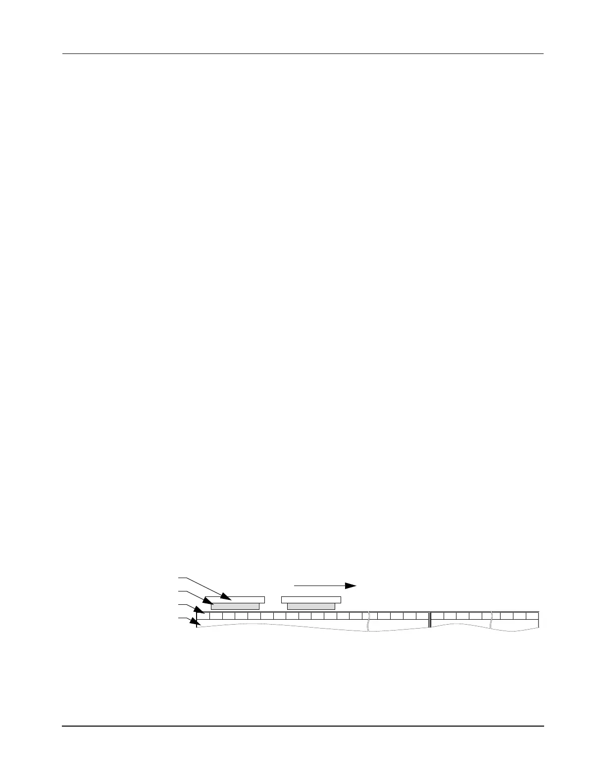
Motor Topology
Each MagneMover LITE motor is constructed as a series of blocks (see Table 3-2 on page 82
and Figure 6-2). Each block is a discrete motor primary section within the motor consisting of
one coil that is energized as required. Varying the magnetic force within a block and its neigh-
bors causes the vehicle to move in the desired direction and provides precise positioning of
the vehicles.
Figure 6-2: Representation of Stationary Vehicles and Motor Blocks
The control software makes sure that the vehicle cannot get closer than 1.5 mm [0.0.6 in] to
the end of a block it is over unless the vehicle has permission to enter the next block. Because
of this control feature, the minimum distance between vehicles on adjacent motor blocks is
3 mm [0.12 in] when not moving. However, this dimension is variable depending upon the
Vehicle
Motor
Block
Magnet Array
Downstream
 Loading...


