Installation
Transport System Installation
MagneMover LITE User Manual 257
Rockwell Automation Publication MMI-UM002F-EN-P - October 2022
2. Locate the motor or switch so that the protruding boss on the standard motor mount is
keyed into the beam and aligned to the T-nut. Install an M8 x 20 mm bolt and M8 split
lock washer as shown in Figure 5-10 and finger tighten.
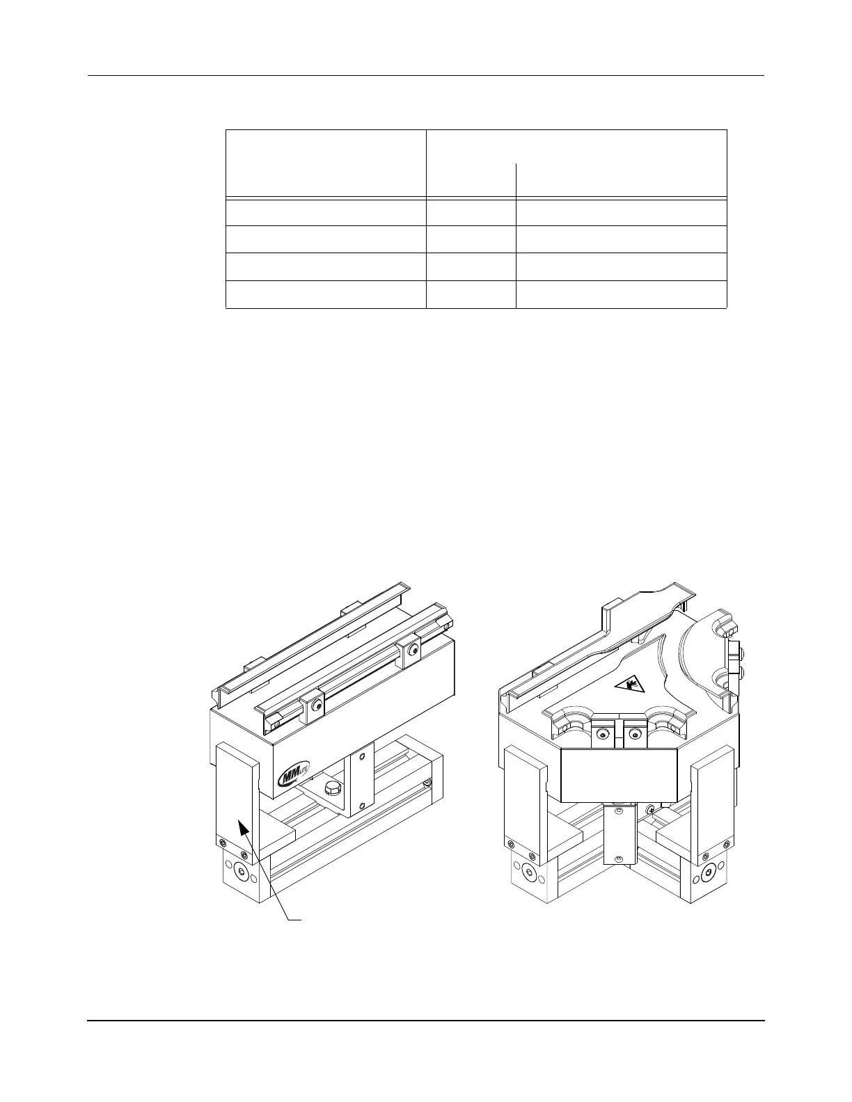
3. Using the Motor Alignment Fixture, adjust the position of the motor or switch along
the beam so it is properly centered on the beam as shown in Figure 5-11. Make sure
that the fixture is fully seated in the slot in the beam. For switches, also adjust the posi-
tion of the switch on the motor mount to make sure that the third face is properly posi-
tioned. Tighten the M8 bolt to 26 N•m [230 in•lb] with a 13 mm Hex socket to secure
the motor mount to the beam.
Figure 5-11: Positioning Motors and Switches
4. Continue to install motors and switches as described in Step 2, at every third motor
verify the position of the motor as described in Step 3.
Table 5-2: Motor Mount Reference
Motor Type
Motor Mount
Qty Location
250 mm Motor 1 Center of beam
1000 mm Motor 2 250 mm from each end of beam
125 mm R 90° Curve Motor 1 Center of beam
*
* Make sure that the beam is oriented so that all internal fastening hardware is on the bot-
tom of the beam.
Left or Right Switch 1 Center of beam
 Loading...


